
Ⅰ.Product Introduction
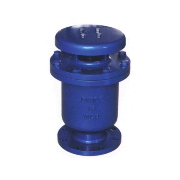
The CARX-1.0 Composite Rapid Air Vent (inlet) Valve is a key component designed for pipeline systems, specifically installed at the highest point of pipelines, gas-confined locations, or pump outlets. Its core functions are to eliminate gas accumulation in pipelines and ensure the unimpeded operation of the pipeline system. Without this exhaust valve, pipelines may face frequent malfunctions, resulting in the actual water capacity failing to meet the designed requirements, which directly affects the normal operation of the entire pipeline system.
In addition to exhaust, this valve also plays a crucial role in pipeline safety protection. In the event of power outages during operation, pipeline displacement, or ruptures, the exhaust and intake valve can quickly introduce air into the pipeline. This effectively prevents pipeline vibration or further rupture caused by negative pressure inside the pipeline, providing reliable safety guarantee for the stable operation of the pipeline system.
Ⅱ.Product Features
-
Dual-hole Exhaust & Intake Design: Equipped with two holes (one large and one small) to adapt to different working scenarios. The large hole, whose diameter is basically equivalent to the pipeline diameter, is used for discharging a large amount of gas in the pipeline during the initial operation stage, realizing rapid exhaust and ensuring the pipeline can quickly enter the normal operation state.
-
Continuous Micro-exhaust Function: After the large amount of initial gas is discharged, the large hole stops exhausting automatically. During the normal operation of the pipeline, the naturally generated residual gas will gradually accumulate and concentrate at the upper part of the pipeline, which affects the water output efficiency. The small hole of the valve can continuously discharge these residual gases, maintaining the optimal operating state of the pipeline.
-
Rapid Negative Pressure Protection: When negative pressure occurs in the pipeline (such as power outages, pump shutdowns, or sudden emptying of water flow), the floating ball inside the valve drops rapidly, opening the large hole to quickly introduce a large amount of air into the pipeline. This timely relieves the negative pressure, effectively preventing pipeline damage caused by negative pressure suction.
-
Stable Sealing Performance: Adopts high-quality sealing materials and precision structural design. Under the condition of meeting the working pressure requirements, it can ensure good sealing performance, reducing the risk of leakage and ensuring the stability of the pipeline system.
-
Adaptable to Municipal Water Supply Scenarios: Specifically designed for branch water media, it can operate stably at normal atmospheric temperature, fully meeting the use needs of municipal water supply and other related pipeline systems.
Ⅲ.Technical Data Summary
1. Working Principle
The composite exhaust valve is equipped with two holes (one large and one small) as its core working structure. During the initial commissioning of the pipeline, a large amount of gas is present inside the pipeline, and these gases are quickly discharged through the large hole (whose diameter is basically the same as that of the pipeline). After the large amount of gas is discharged, the large hole automatically stops exhausting, and the pipeline enters a normal operation state.
During the normal operation of the pipeline, residual gas will be naturally generated due to various factors. These gases will gradually accumulate and grow, concentrating at the upper part of the pipeline and affecting the water output efficiency of the pipeline. The small hole of the valve continuously discharges these residual gases to avoid the adverse effects of gas accumulation.
In special cases such as power outages, pump shutdowns, or pipeline water flow emptying, negative pressure will quickly form inside the pipeline. At this time, the floating ball inside the valve will drop under the action of negative pressure, opening the large hole to allow a large amount of air to enter the pipeline quickly. This timely relieves the negative pressure inside the pipeline, ensuring the safety of the pipeline and preventing vibration or rupture.
2. Key Notes for Use
-
During the use of the exhaust valve, the working pressure should not be lower than 0.02MPa. If the pressure is lower than 0.02MPa, the valve is prone to leakage, which affects the normal operation of the pipeline system.
-
The modified exhaust valve must be equipped with a maintenance valve. This facilitates daily inspection, maintenance, and repair of the exhaust valve without affecting the normal operation of the entire pipeline system.
3. Technical Parameters
|
Parameter Item
|
Specification
|
|---|---|
|
Working Pressure
|
1.0MPa
|
|
Medium
|
Branch Water
|
|
Operating Temperature
|
Normal Atmospheric Temperature
|
|
Valve Body Material
|
HT200
|
|
Floating Ball and Plug Head Material
|
Iron Casting, 304 Stainless Steel
|
|
Sealing Material
|
Acrylonitrile-butadiene Rubber
|
Ⅳ.The main shape and connection size
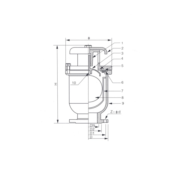
| Number of cartridges | D | D1 | D2 | Φ | H | ZΦd |
| 25 | 115 | 85 | 68 | 195 | 320 | 4-14 |
| 50 | 160 | 125 | 100 | 195 | 320 | 4-18 |
| 80 | 195 | 160 | 135 | 242 | 375 | 4-18 |
| 100 | 215 | 180 | 155 | 260 | 395 | 8-18 |
| 150 | 280 | 240 | 210 | 340 | 500 | 8-23 |
| 200 | 335 | 295 | 265 | 405 | 600 | 8-23 |
| 250 | 390 | 350 | 320 | 465 | 680 | 12-23 |
| 300 | 440 | 400 | 368 | 505 | 780 | 12-23 |
| 350 | 500 | 460 | 428 | 605 | 860 | 16-23 |
| 400 | 565 | 515 | 482 | 660 | 940 | 16-25 |


