
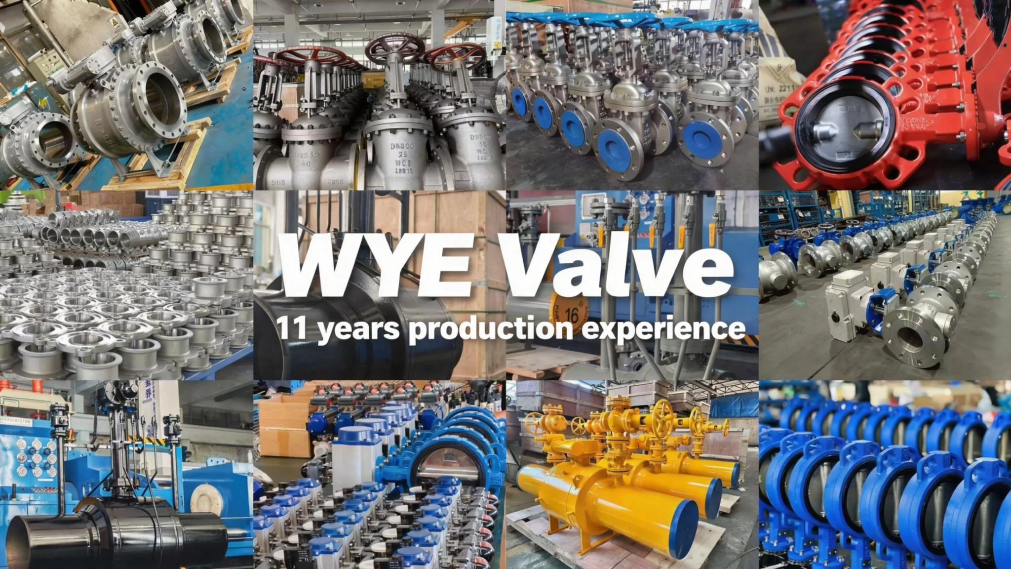
I. Product Introduction
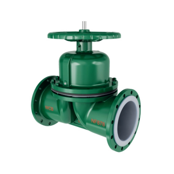
The Manual Diaphragm Valve (Weir Type) with flange connection is a specialized control valve designed for precise on-off and throttling control of various media in industrial pipelines. It features a weir-type structure and fully lined design, which effectively isolates the valve’s internal metal components from the medium, ensuring excellent corrosion resistance and pollution-free transportation of the medium. This series of valves is available in nominal diameters ranging from DN15 to DN300 and nominal pressures from PN0.6 to 1.6 MPa, covering a wide range of industrial application scenarios.
The basic models of the fully lined manual weir-type diaphragm valve include G41PFA-10C, G41F46-10C, G41F4-10C, and G41Po-10C. These models are differentiated by the material of the lining and diaphragm, allowing users to select the most suitable configuration according to the characteristics of the conveyed medium (such as corrosiveness, temperature, and viscosity). It is widely used in chemical, petroleum, pharmaceutical, food and beverage, water treatment, and other industries, especially suitable for working conditions involving strong corrosive media, high-purity media, or media containing suspended particles.
II. Product Features
-
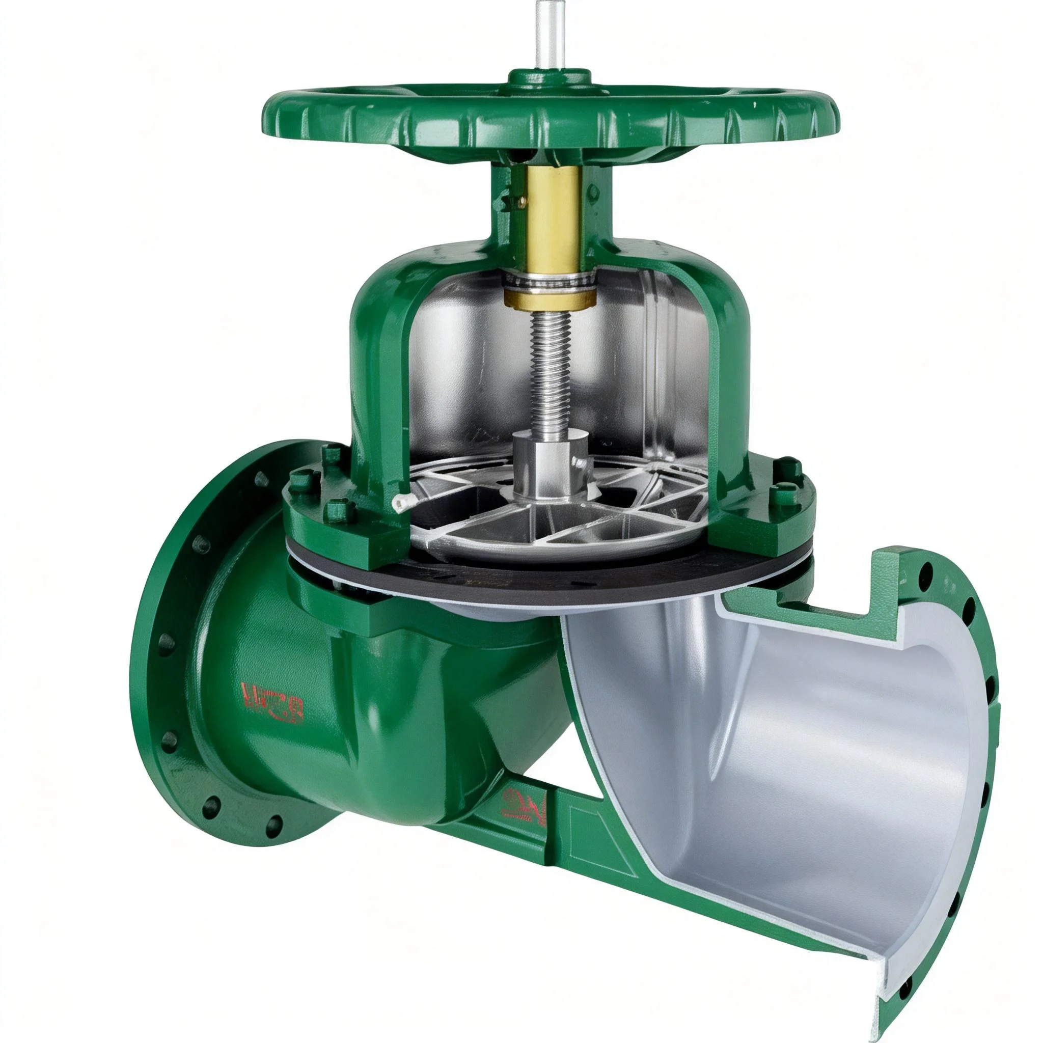
Excellent Corrosion Resistance: The valve adopts a fully lined structure, with lining materials including FEP (F46), PCTFE (F3), PTFE (F4), and PO. The diaphragm is made of PTFE (F46) or CR neoprene, which can resist the erosion of most strong acids, alkalis, salts, and organic solvents. The metal parts (valve body, bonnet, tappet, etc.) are available in gray cast iron (HT250), carbon steel (WCB), and stainless steel (CF8) to meet the requirements of different working environments.
-
Good Sealing Performance: Relying on the elastic deformation of the diaphragm, the valve achieves tight sealing between the diaphragm and the weir surface. There is no leakage between the valve core and the valve seat, ensuring zero internal leakage under normal working conditions. At the same time, the flange connection adopts standard sealing structures, effectively preventing external leakage of the medium.
-
Simple Structure & Easy Operation: The valve is manually operated through a handwheel, with a simple and compact overall structure, small size, and light weight. The operation is straightforward, requiring only rotating the handwheel to adjust the opening and closing of the valve, which is convenient for on-site operation and maintenance. The handwheel is made of HT200 or WCC, featuring high strength and good wear resistance.
-
Stable Working Performance: The weir-type flow channel design ensures smooth medium flow, low flow resistance, and small pressure loss, which helps to maintain the stability of the pipeline system. The tappet is made of 35# steel, 1Cr13, or 1Cr18Ni19, with high rigidity and wear resistance, ensuring long-term stable operation of the valve. Nuts are made of 45# steel or 0Cr18Ni9, with reliable connection performance.
-
Wide Application Range: With nominal diameter covering DN15~300 and nominal pressure ranging from PN0.6~1.6 MPa, it can adapt to different pipeline specifications and working pressure requirements. The diverse selection of lining and metal materials enables the valve to be applied to various media, including corrosive, high-purity, and particulate-containing media.
-
Compliance with Strict Standards: The product is designed and manufactured in strict accordance with national and industry standards such as GB/T12239, ensuring stable and reliable product quality. The structure length, flange size, pressure test, and other indicators all comply with corresponding standard requirements, facilitating interchangeability and installation with other pipeline components.
III. Technical Data
1. Basic Parameters
-
Valve Type: Manual Weir-Type Diaphragm Valve (Flange Connection, Fully Lined)
-
Nominal Diameter: DN15 ~ 300 mm
-
Nominal Pressure: PN0.6 ~ 1.6 MPa
-
Basic Models (Fully Lined): G41PFA-10C, G41F46-10C, G41F4-10C, G41Po-10C
2. Main Parts and Components Material
|
Serial Number
|
Part Name
|
Gray Cast Iron (Z)
|
Carbon Steel (C)
|
Stainless Steels (P)
|
|---|---|---|---|---|
|
1
|
Valve body, bonnet, flap
|
HT250
|
WCB
|
CF8
|
|
2
|
Tappet
|
–
|
35
|
1Cr13, 1Cr18Ni19
|
|
3
|
Liner
|
FEP (F46), PCTFE (F3), PTFE (F4), PO
|
||
|
4
|
Diaphragm sheet
|
PTFE (F46)/CR neoprene
|
||
|
5
|
Nut (female component of nut and bolt)
|
45
|
45
|
0Cr18Ni9
|
|
6
|
Handwheels
|
HT200
|
HT200
|
WCC
|
3. Implementation Standards
-
Design and Manufacturing: GB/T12239
-
Structure Length: HG/T 3704
-
Flange Size: HG/T 20592 (or as required by the contract)
-
Pressure Test: GB/T 13927
-
Symbolize: GB/T 12220
-
Fill: GB/T 12252
Ⅳ.The main shape and connection size
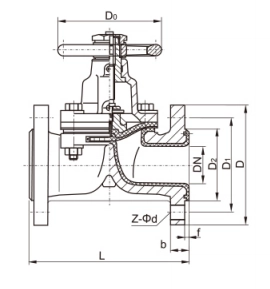
Main connection dimensions and weight
Main connection dimensions and weight
Main connection dimensions and weight


