
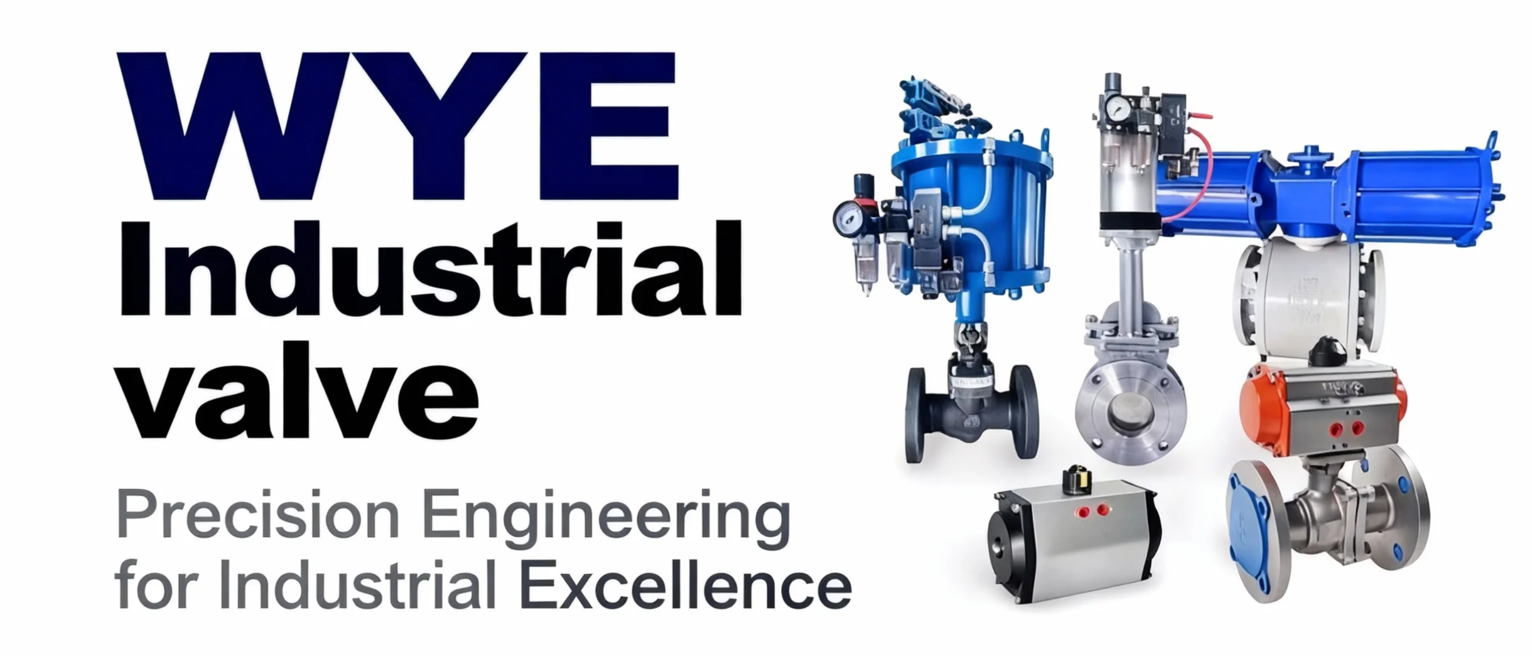
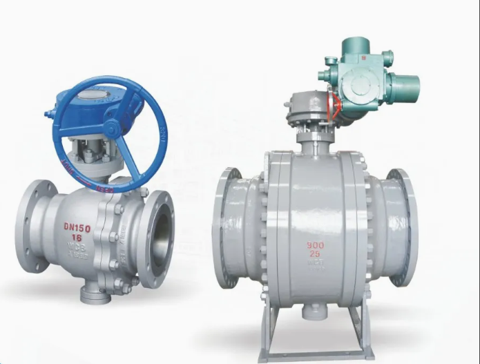
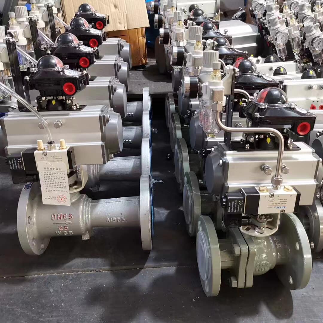
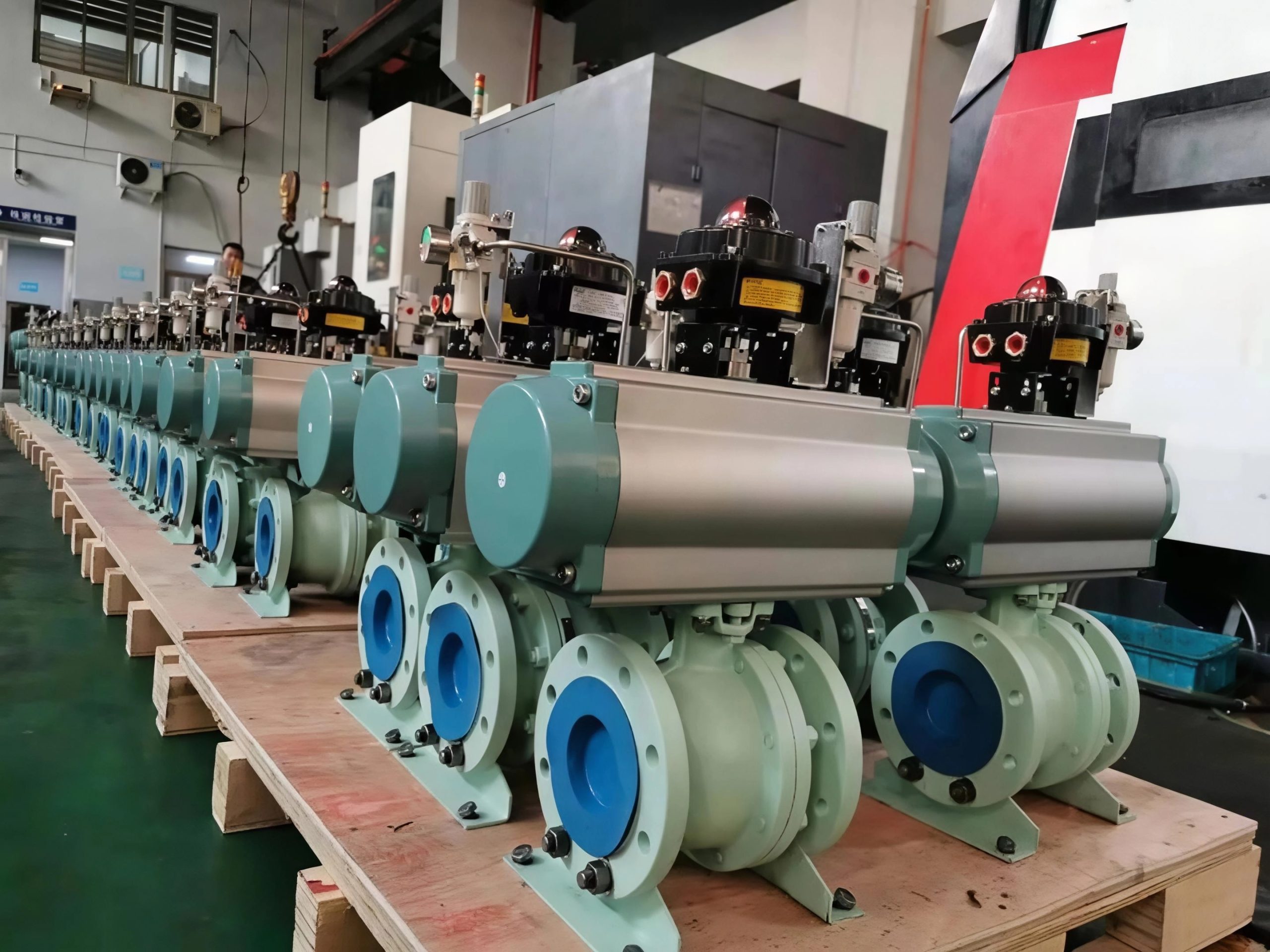
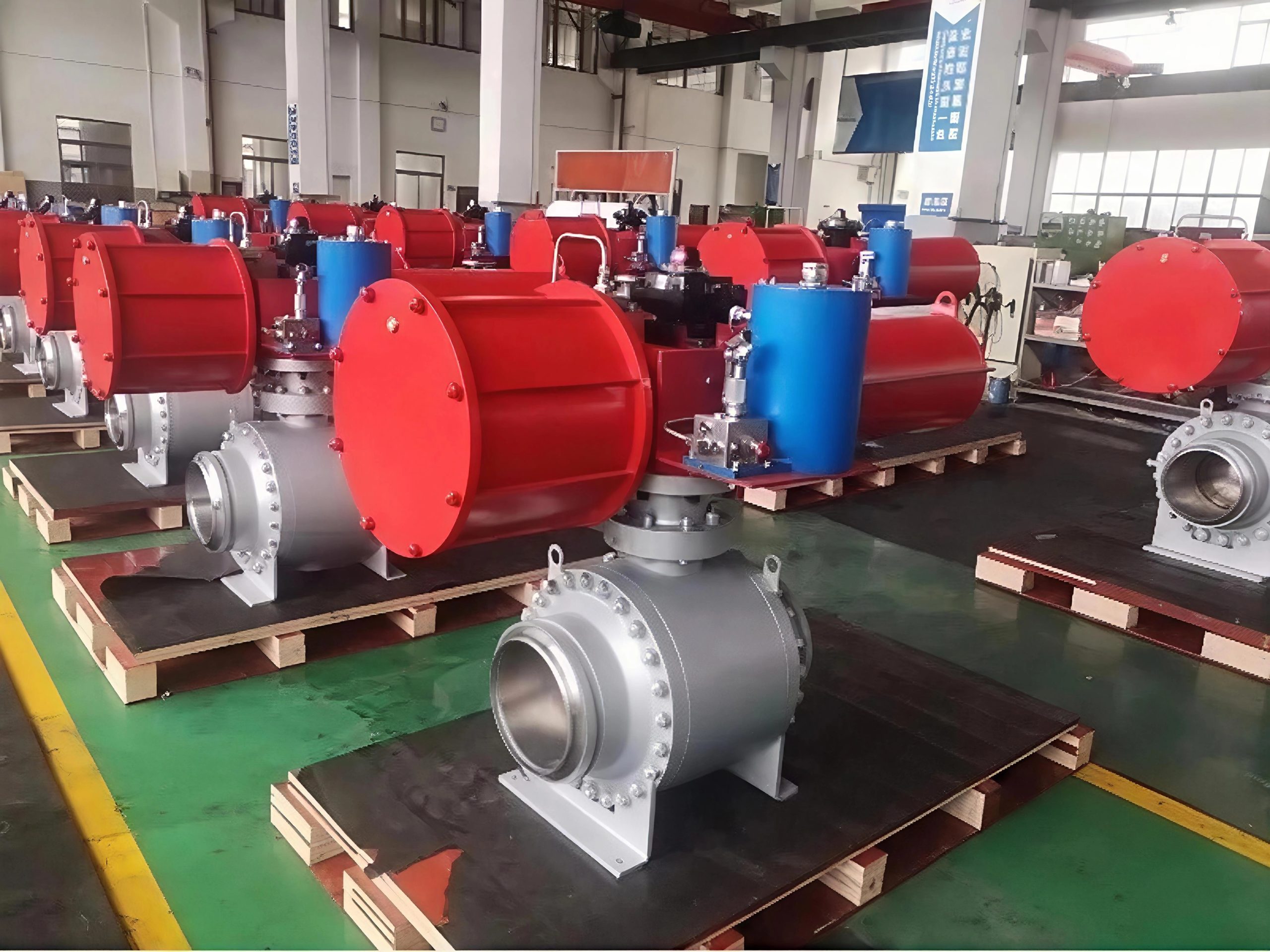
一.Product Introduction
The Q340HYF eccentric hemispherical valve is a top – notch choice for fluid control. It uses an eccentric tightening structure with a metal hard – seal pair, ensuring smooth flow and no scouring when opened or closed, ideal for scaling – prone two – phase streams. Bimetal hemispheres and specially treated valve seats offer anti – corrosion, wear – resistance, etc. It achieves zero leakage of harmful gases. With a compensable valve core, it lasts long, and the valve seat is reusable. Suitable for sewage, oil, gas, slurry, and pulverized coal ash systems, meeting strict industrial needs.
二.Product Features
1. Small flow resistance. The medium channel inside the valve body is straight, the medium flows in a straight line, and the flow resistance is small.
2. Less effort when opening and closing. It is compared with the globe valve, because whether it is open or closed, the direction of movement of the gate is perpendicular to the direction of medium flow.
3. Large height and long opening and closing time. The opening and closing stroke of the gate is relatively large, and the lifting is carried out by the screw.
4. Water hammer is not easy to produce. The reason is the long closing time.
5. The medium can flow in any direction on both sides, easy to install. Both sides of the gate valve channel are symmetrical.
6. The structural length (the distance between the two connecting end faces of the shell) is small.
7. Simple shape, short structure length, good manufacturing technology and wide application range.
8. Compact structure, good valve rigidity, smooth passage, small flow resistance, stainless steel and hard alloy sealing surface, long service life, PTFE packing, reliable sealing, light and flexible operation.
三.Technical data
| Parameter | Details |
| Nominal pressure (Mpa) | 0.6, 1.0, 1.6, 2.5, 4.0 |
| Nominal diameter (mm) | 40 – 1600, 40 – 1600, 40 – 1200, 40 – 600, 40 – 600 |
| Sealing test pressure (Mpa) | 0.66, 1.1, 1.76, 2.75, 4.4 |
| Shell test pressure (Mpa) | 0.9, 1.5, 2.4, 3.75, 6.0 |
| Applicable temperature (°C) | -29 ~ 300, -29 ~ 425, -29 ~ 540 |
| Applicable media | Clear water, seawater, sewage, acid – alkali, slurry, steam, gas, oil |
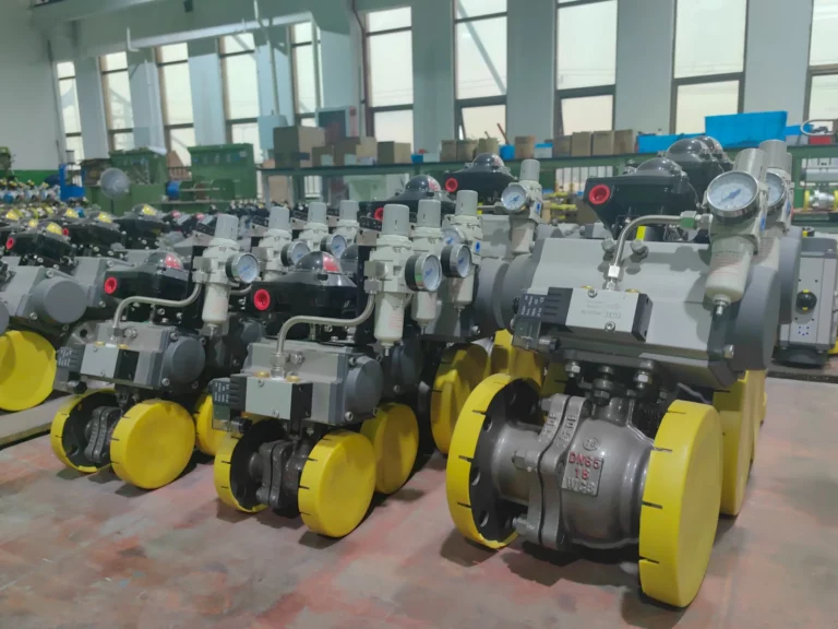
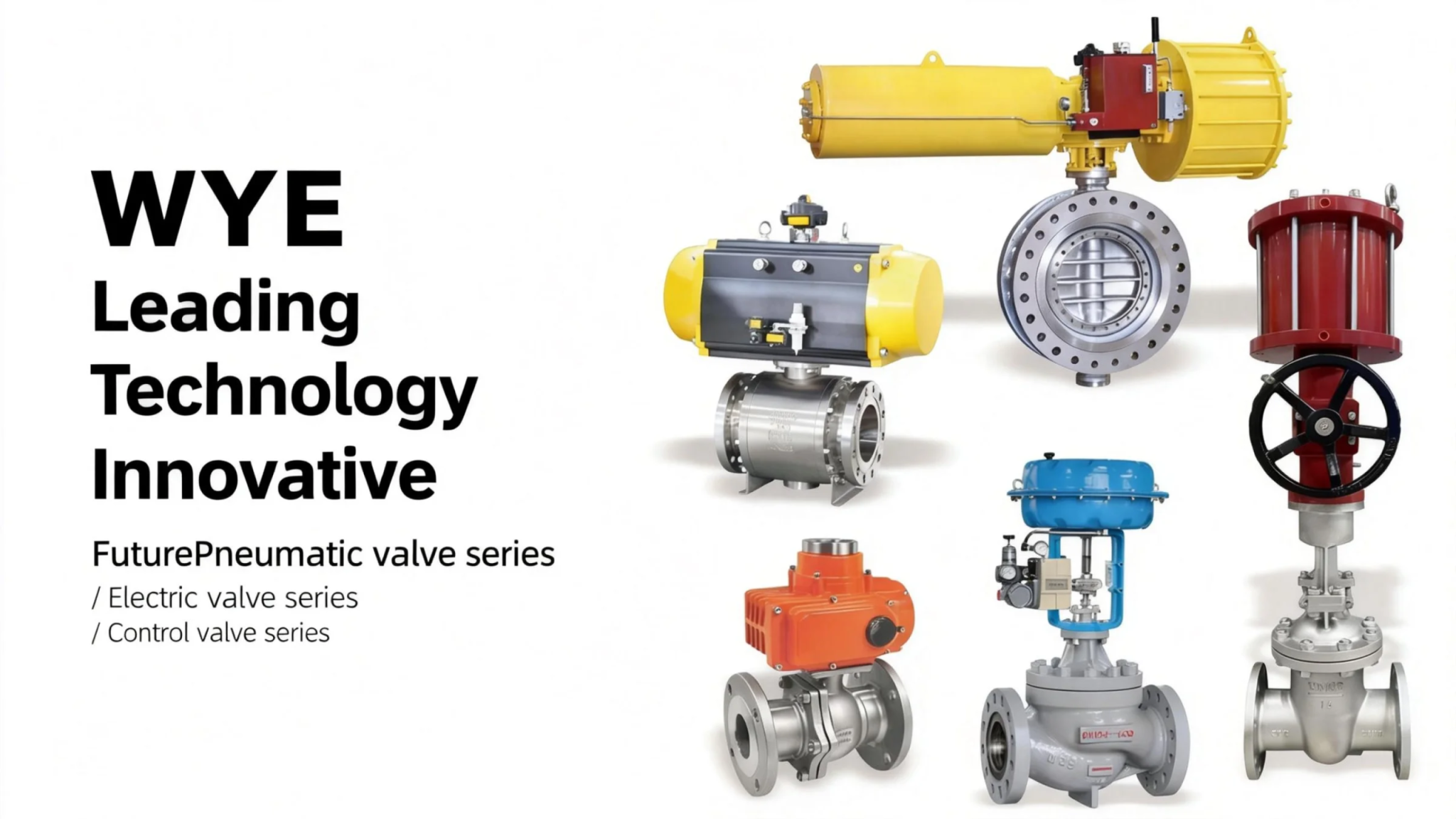
| Drive mode | Manual, electric, pneumatic |
| Connection form | Flange connection, clamp connection |
| Installation method | Vertical installation, horizontal installation |
四.The main shape and connection size
| Nominal pressure PN/MPa | Nominal diameter DN/mm | Size (mm) | |||||||
| L | D | K | d | f | C | Z – Φd | H | ||
| 1.6 | 40 | 165 | 150 | 110 | 85 | 3 | 16 | ||
| 50 | 178 | 165 | 125 | 100 | 4 – Φ18 | ||||
| 65 | 190 | 185 | 145 | 120 | 18 | 280 | |||
| 80 | 203 | 200 | 160 | 135 | 20 | 320 | |||
| 100 | 229 | 220 | 180 | 155 | 8 – Φ18 | 370 | |||
| 125 | 254 | 250 | 210 | 185 | 22 | 430 | |||
| 150 | 267 | 285 | 240 | 210 | 24 | 8 – Φ23 | 510 | ||
| 200 | 292 | 340 | 295 | 265 | 26 | 12Φ – 23 | 600 | ||
| 250 | 330 | 405 | 355 | 320 | 30 | 12 – Φ26 | 690 | ||
| 300 | 502 | 460 | 410 | 375 | 4 | 760 | |||
| 350 | 572 | 520 | 470 | 435 | 34 | 16 – Φ26 | 830 | ||
| 400 | 610 | 580 | 525 | 485 | 36 | 16 – Φ30 | 925 | ||
| 450 | 660 | 640 | 585 | 545 | 40 | 20 – Φ30 | 1025 | ||
| 500 | 700 | 715 | 650 | 608 | 44 | 20 – Φ34 | 1120 | ||
| 600 | 813 | 840 | 770 | 718 | 5 | 48 | 20 – Φ36 | 1210 | |


