
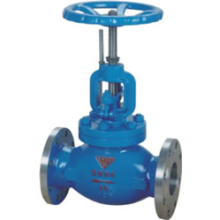
一.Product Introduction
T40H Manual Flow Regulating Valve manufacturer, factory and supplier. T40H Manual Flow Regulating Valve is a special function regulating valve that, in addition to its regulating valve function, can also achieve flow quantization. T40H Manual Flow Regulating Valve can effectively solve the problem of uneven room temperature in heating (air conditioning) systems. Due to the fact that this valve is equipped with an opening degree indicator, a locking device for the opening degree, and a pressure measurement valve for flow measurement, as long as the appropriate scale balance valve is installed on each branch and the user’s entrance, and the special intelligent instrument is used for one-time calibration and locking, the total water volume of the system can be controlled within a reasonable range, thereby overcoming the unreasonable phenomenon of “large flow and small temperature difference” and becoming an ideal product for heating systems.
T40H Manual Flow Regulating Valve can be installed on the supply pipe or the return pipe, but it is usually installed on the return pipe. Especially for high-temperature circuits, T40H Manual Flow Regulating Valve is more convenient for commissioning if it is installed on the return pipe. After installing the balancing valve on the supply and return pipes, there is no need to install the stop valve.
二.Product Features
1.Improve heating and supply conditions: All branch lines and heat points that use manual regulating valves can adjust the flow rate according to the design working conditions to achieve good temperature working conditions. This kind of regulating valve has better regulating performance than gate valves and globe valves, and it has similar linear regulating performance.Therefore, the unevenness of heat and cold in various heating buildings has been effectively improved.
2.Energy saving: Due to temperature and pressure imbalance in the heat pipe network, the flow rate of some branches is too large, and the temperature of some buildings is too high. Users have to open windows to save energy.
3.Improve the hydraulic working conditions of the network management: The manual control valve can be controlled according to the rated flow rate, which reduces the flow rate of excessive operation of the network management, and improves the degree of deterioration of the original water working conditions to a certain extent.
三.Technical data
| Model number | PN | Working pressure/MPa | Applicable temperature/℃ | Applicable media |
| T40H-10 | 10 | 1.0 | ≤200 | Water, steam |
| T40H-16 | 16 | 1.6 | ||
| T40H-25 | 25 | 2.5 |
| Model number | Material | ||
| Valve body, valve cover, packing gland, handwheel | Valve stem, valve disc sealing ring | Indicator plate, stem nut, nut sleeve | |
| T40H-10 | Gray cast iron, (cast steel) | Stainless steel | Brass |
| T40H-16 | |||
| T40H-25 | |||
四.The main shape and connection size
| DN | L | D | D1 | D2 | f | b | H | H1 | D0 | z×Φd | weight/kg |
| 250 | 730 | 395 | 350 | 320 | 3 | 28 | 914 | 1074 | 500 | 12×Φ22 | 327 |
| 300 | 850 | 445 | 400 | 370 | 4 | 28 | 914 | 1074 | 500 | 12×Φ22 | 422 |
| 350 | 980 | 505 | 460 | 430 | 4 | 30 | 968 | 1168 | 500 | 16×Φ22 | 610 |
| 400 | 991 | 565 | 515 | 482 | 4 | 32 | 968 | 1168 | 500 | 16×Φ26 | 750 |
| 450 | 1092 | 615 | 565 | 532 | 4 | 32 | 1100 | 1350 | 680 | 20×Φ26 | 999 |
| 500 | 1194 | 670 | 620 | 585 | 4 | 34 | 1100 | 1350 | 680 | 20×Φ26 | 999 |
| DN | L | D | D1 | D2 | f | b | H | H1 | D0 | z×Φd | weight/kg |
| 15 | 130 | 95 | 65 | 47 | 2 | 14 | 160 | 172 | 65 | 4×Φ13.5 | 2.5 |
| 20 | 150 | 105 | 75 | 58 | 2 | 16 | 160 | 172 | 65 | 4×Φ13.5 | 3.5 |
| 25 | 160 | 115 | 85 | 68 | 2 | 16 | 182 | 195 | 80 | 4×Φ13.5 | 4.8 |
| 32 | 180 | 140 | 100 | 78 | 2 | 18 | 192 | 210 | 80 | 4×Φ13.5 | 7 |
| 40 | 200 | 150 | 110 | 88 | 3 | 18 | 250 | 273 | 120 | 4×Φ13.5 | 9.5 |
| 50 | 230 | 165 | 125 | 102 | 3 | 20 | 264 | 290 | 120 | 4×Φ17.5 | 13.5 |
| 65 | 290 | 185 | 145 | 122 | 3 | 20 | 380 | 426 | 200 | 4×Φ17.5 | 29 |
| 80 | 310 | 200 | 160 | 133 | 3 | 22 | 413 | 468 | 200 | 8×Φ17.5 | 35 |
| 100 | 350 | 220 | 180 | 158 | 3 | 24 | 466 | 530 | 240 | 8×Φ17.5 | 56 |
| 125 | 400 | 250 | 210 | 184 | 3 | 26 | 540 | 613 | 260 | 8×Φ17.5 | 79 |
| 150 | 480 | 285 | 240 | 212 | 3 | 26 | 623 | 698 | 360 | 8×Φ22 | 117 |
| 200 | 600 | 340 | 295 | 268 | 3 | 30 | 687 | 777 | 400 | 12×Φ22 | 185 |
| 250 | 730 | 395 | 350 | 320 | 3 | 30 | 940 | 1074 | 500 | 12×Φ22 | 327 |
| 300 | 850 | 445 | 460 | 430 | 4 | 30 | 940 | 1074 | 500 | 12×Φ22 | 422 |
| DN | L | D | D1 | D2 | f | b | H | H1 | D0 | z×Φd | weight/kg |
| 15 | 130 | 95 | 65 | 47 | 2 | 16 | 160 | 172 | 65 | 4×Φ13.5 | 2.5 |
| 20 | 150 | 105 | 75 | 58 | 2 | 18 | 160 | 172 | 65 | 4×Φ13.5 | 3.5 |
| 25 | 160 | 115 | 85 | 68 | 2 | 18 | 182 | 195 | 80 | 4×Φ13.5 | 4.8 |
| 32 | 180 | 140 | 100 | 78 | 2 | 20 | 192 | 210 | 80 | 4×Φ13.5 | 7 |
| 40 | 200 | 150 | 110 | 88 | 3 | 20 | 250 | 273 | 120 | 4×Φ17.5 | 9.5 |
| 50 | 230 | 165 | 125 | 102 | 3 | 22 | 264 | 290 | 120 | 4×Φ17.5 | 13.5 |
| 65 | 290 | 185 | 145 | 122 | 3 | 24 | 380 | 426 | 200 | 8×Φ17.5 | 29 |
| 80 | 310 | 200 | 160 | 133 | 3 | 26 | 413 | 468 | 200 | 8×Φ17.5 | 35 |
| 100 | 350 | 235 | 190 | 158 | 3 | 28 | 466 | 530 | 240 | 8×Φ22 | 56 |
| 125 | 400 | 270 | 220 | 184 | 3 | 30 | 540 | 613 | 260 | 8×Φ26 | 79 |
| 150 | 480 | 300 | 250 | 212 | 3 | 34 | 623 | 698 | 360 | 8×Φ26 | 117 |
| 200 | 600 | 360 | 310 | 278 | 3 | 34 | 687 | 777 | 400 | 12×Φ26 | 185 |


