
一.Product Introduction
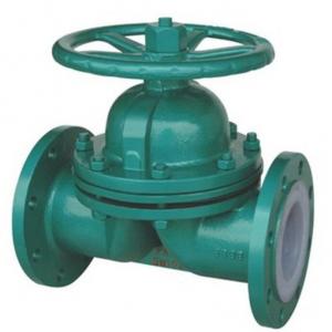
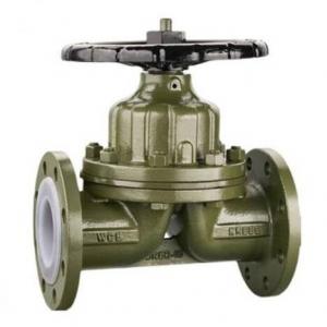
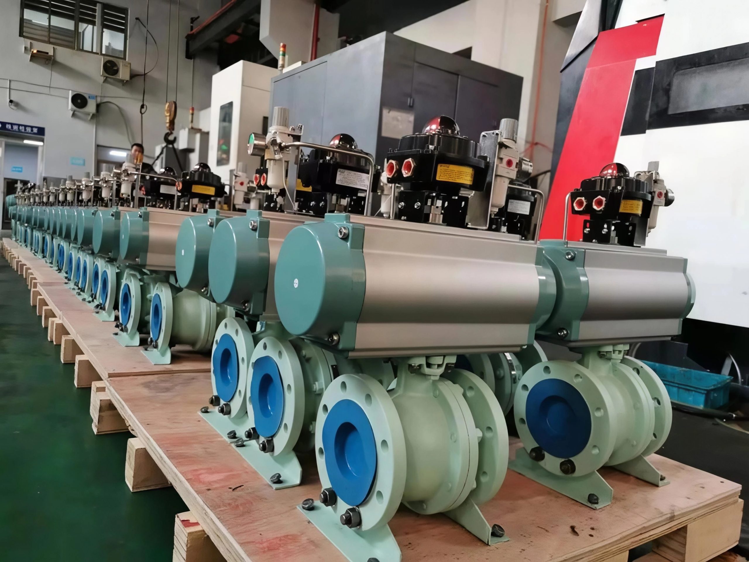
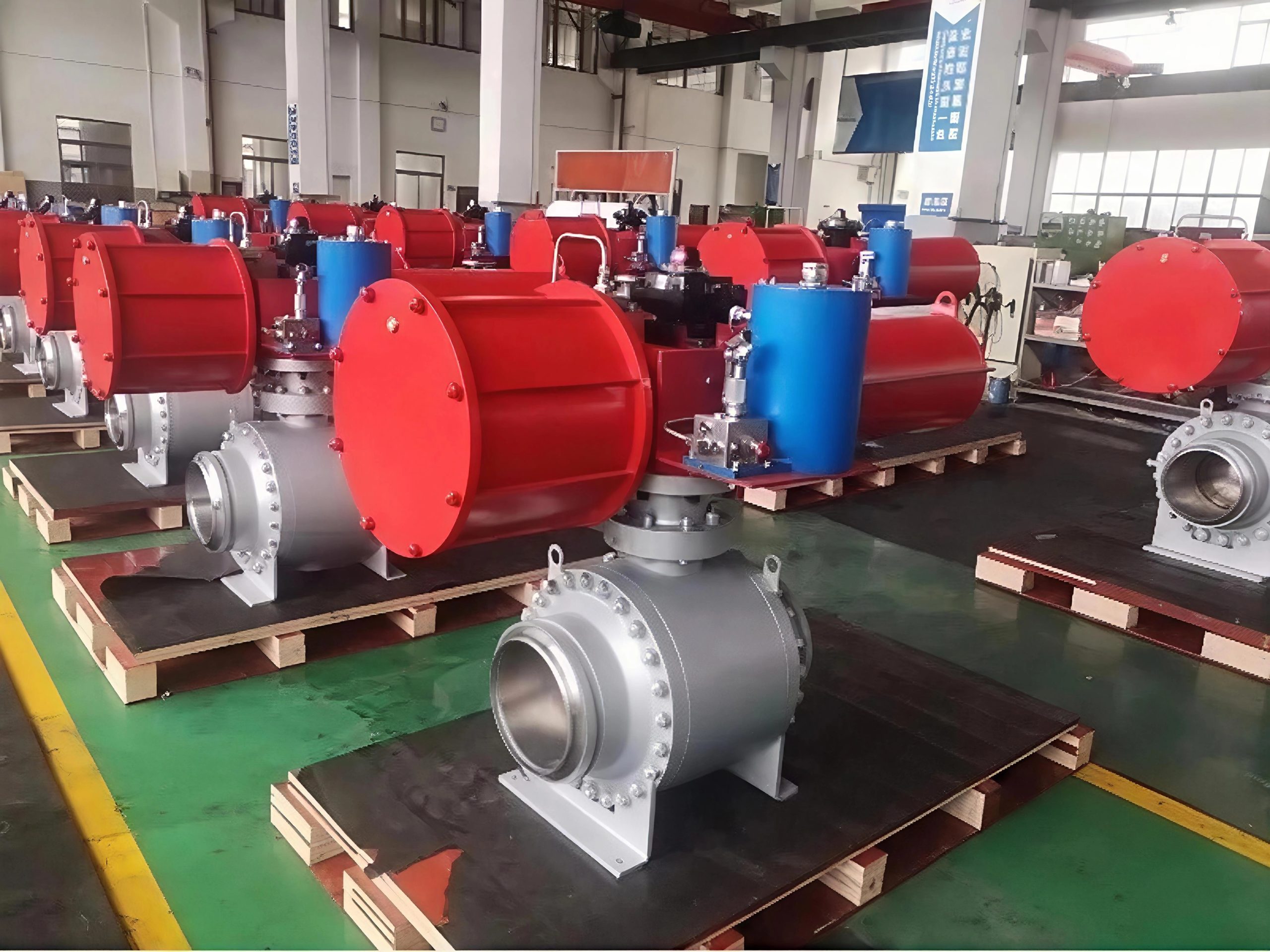
The G41F46 Fluorine Lined Diaphragm Valve is a high-performance valve engineered for handling corrosive media in various industrial applications. With its fluorine lining, it offers exceptional resistance to a wide range of aggressive chemicals, ensuring reliable and long-lasting service. Available in sizes from DN15 to 300mm and capable of withstanding a pressure of 1.6MPa, this valve is suitable for diverse piping systems. It can be constructed from materials such as WCB, stainless steel, carbon steel, and cast iron, providing flexibility to meet different operational requirements. Whether in chemical processing, pharmaceutical production, or other industries dealing with corrosive fluids, the G41F46 valve delivers efficient and dependable flow control.
二.Product Features
1. The difference between G41F46 PTFE FEP lined diaphragm valve and other valves is that: the structure of no packing box; G41F46 fluorine lined diaphragm valve diaphragm can make the corrosive medium in the flow channel and all the driving components in a completely isolated state, so as to eliminate the usual valve “run, take, drop, leakage” and other drawbacks.
2. Due to the smooth flow path of the diaphragm valve, the flow resistance is small, so the larger flow rate can be obtained.
3. The body cavity of G41F46 PTFE FEP lined diaphragm valve is lined with PTFE or FEP. Therefore, it has superior corrosion resistance.
4. Because the sealing parts are elastic tetrafluorodiaphragm. Therefore, it also has better sealing and closing force.
5. G41F46 PTFE FEP lined diaphragm valve is composed of valve body, valve cover, disc, stem, diaphragm and other driving parts.
6. The opening and closing of G41F46 PTFE FEP lined diaphragm valve are achieved by rotating the hand wheel. The valve is marked on the upper end of the valve cover with visible valve opening or closing position display color, to indicate the valve opening and closing stroke. When the hand wheel is placed clockwise, the hand wheel moves down, and the disc drives the diaphragm down to cut off the path; On the contrary, the valve is opened and the color is revealed.
7. G41F46 PTFE FEP lined diaphragm valve adopts standard: in accordance with the provisions of GB12239, and in accordance with BS5156.
8. Non-toxic: with physiological inertia, can be used for food sanitation pipeline.
9.No leakage: Body packing design prevents fluid from leaking at stem.
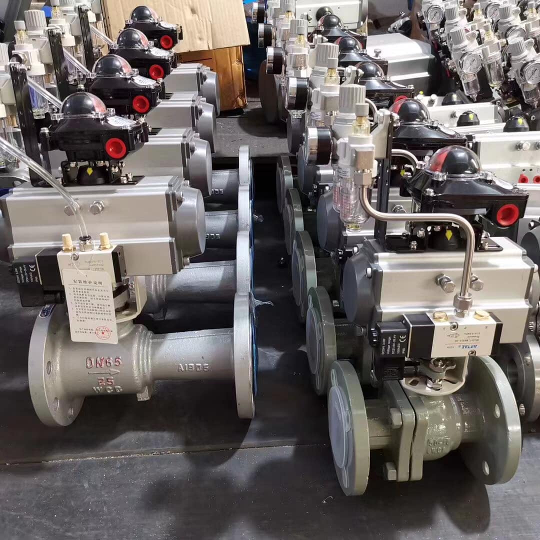
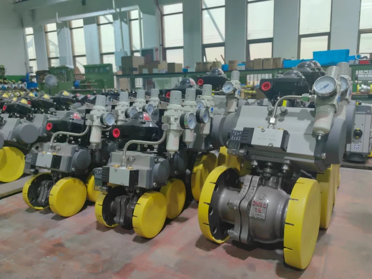
10.Remote control can be realized by adding pneumatic actuator.
三.Technical data
| G41F46 Fluorine Lined Diaphragm Valve Specifications | |
| Nominal pressure: | 1.6 Mpa |
| Strength test: | 2.4Mpa |
| Seal test: | 1.8Mpa |
| Gas seal test: | 0.6MP |
| Valve body material: | WCB(C) / CF8 (P) / CF3 (PL) / CF8M (R) / CF3M (RL) |
| Suitable medium: | water / steam / oil products / nitric acid / acetic acid |
| Suitable temperature: | -40℃~+150℃ |
| NO. | Part name | Material |
| 1 | Body | cast iron/WCB/304/306 |
| 2 | Seals | PTFE |
| 3 | Bonnet | cast iron/WCB/304/306 |
| 4 | Disc | cast iron/WCB/304/306 |
| 5 | Gland | WCB/304/306 |
| 6 | Stem | cast iron/WCB/304/306 |
| 7 | Handle | WCB |
| 8 | Diaphragm | FEP |
| 9 | Support | PTFE |
四.The main shape and connection size
| G41F46 Fluorine Lined Diaphragm Valve Main Dimensions And Connection Dimensions | ||||||||||||
| nominal diameter | standard value | reference value | ||||||||||
| DN(mm) | NPS(inch) | L | D | D1 | D2 | f | b | z-φd | d0 | H | H1 | W(kg) |
| 0.6MPa/1.0MPa | ||||||||||||
| 15.0 | 1/2 | 125 | 95 | 65 | 45 | 2 | 14 | 4-14 | 100 | 105 | 110 | 3.5 |
| 20.0 | 3/4 | 135 | 105 | 75 | 55 | 2 | 16 | 4-14 | 100 | 115 | 125 | 4 |
| 25.0 | 1.0 | 145 | 115 | 85 | 65 | 2 | 16 | 4-14 | 120 | 120 | 135 | 5.5 |
| 32.0 | 11/4 | 160 | 135 | 100 | 78 | 2 | 18 | 4-18 | 120 | 125 | 150 | 8 |
| 40.0 | 11/2 | 180 | 145 | 110 | 85 | 3 | 18 | 4-18 | 140 | 135 | 175 | 11 |
| 50.0 | 2.0 | 210 | 160 | 125 | 100 | 3 | 20 | 4-18 | 140 | 155 | 195 | 14 |
| 65.0 | 21/2 | 250 | 180 | 145 | 120 | 3 | 20 | 4-18 | 200 | 170 | 200 | 23 |
| 80.0 | 3.0 | 300 | 195 | 160 | 135 | 3 | 22 | 4-18 | 200 | 200 | 255 | 29 |
| 100.0 | 4.0 | 350 | 215 | 180 | 155 | 3 | 22 | 8-18 | 280 | 70 | 325 | 46 |
| 125.0 | 5.0 | 400 | 245 | 210 | 185 | 3 | 24 | 8-18 | 320 | 335 | 405 | 70 |
| 150.0 | 6.0 | 460 | 280 | 240 | 210 | 3 | 24 | 8-23 | 320 | 370 | 450 | 95 |
| 200.0 | 8.0 | 570 | 335 | 295 | 265 | 3 | 26 | 8-23 | 400 | 480 | 600 | 170 |
| 250.0 | 10.0 | 680 | 390 | 350 | 320 | 3 | 28 | 12-23 | 500 | 545 | 620 | 270 |
| 300.0 | 12.0 | 790 | 435 | 395 | 362 | 4 | 34 | 12-23 | 500 | 585 | 680 | 320 |
| 1.6MPa | ||||||||||||
| 15.0 | 1/2 | 130 | 95 | 65 | 45 | 2 | 14 | ’4-14 | 120 | 110 | 115 | 4 |
| 20.0 | 3/4 | 150 | 105 | 75 | 55 | 2 | 16 | ’4-14 | 120 | 120 | 130 | 5 |
| 25.0 | 1.0 | 160 | 115 | 85 | 65 | 2 | 16 | ’4-14 | 140 | 125 | 140 | 6 |
| 32.0 | 11/4 | 180 | 135 | 100 | 78 | 3 | 18 | ’4-18 | 140 | 130 | 155 | 9 |
| 40.0 | 11/2 | 200 | 145 | 110 | 85 | 3 | 18 | ’4-18 | 160 | 140 | 180 | 12 |
| 50.0 | 2.0 | 230 | 160 | 125 | 110 | 3 | 20 | ’4-18 | 160 | 160 | 200 | 15 |
| 65.0 | 21/2 | 290 | 180.0 | 145.0 | 120.0 | 3 | 20 | ’4-18 | 200 | 175 | 205 | 24 |
| 80.0 | 3.0 | 310 | 195 | 160 | 135 | 3 | 22 | ’8-18 | 200 | 205 | 260 | 30 |
| 100.0 | 4.0 | 350 | 215 | 180 | 155 | 3 | 24 | ’8-18 | 280 | 275 | 330 | 48 |
| 125.0 | 5.0 | 400 | 245 | 210 | 185 | 3 | 26 | ’8-18 | 320 | 340 | 410 | 75 |
| 150.0 | 6.0 | 480 | 280 | 240 | 210 | 3 | 28 | ’8-23 | 320 | 375 | 460 | 105 |
| 200.0 | 8.0 | 600 | 335 | 295 | 265 | 3 | 30 | ’12-23 | 400 | 485 | 605 | 182 |
| 250.0 | 10.0 | 730 | 405 | 335 | 320 | 3 | 32 | ’12-25 | 500 | 550 | 625 | 295 |
| 300.0 | 12.0 | 850 | 460 | 410 | 375 | 4 | 34 | ’12-25 | 500 | 590 | 685 | 345 |


