
I. Product Introduction
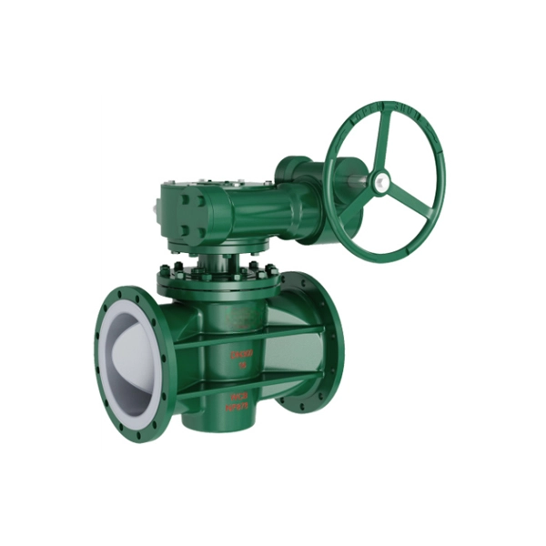
The fully lined ferrule-type flanged plug valve is a specialized control valve designed for harsh working conditions involving corrosive, abrasive, or viscous media. It integrates advanced structural design and high-performance lining materials to achieve reliable sealing, excellent corrosion resistance, and long service life. This valve is widely used in various industrial fields such as chemical engineering, petrochemicals, pharmaceuticals, food processing, and wastewater treatment, where it plays a crucial role in regulating and isolating media flow.
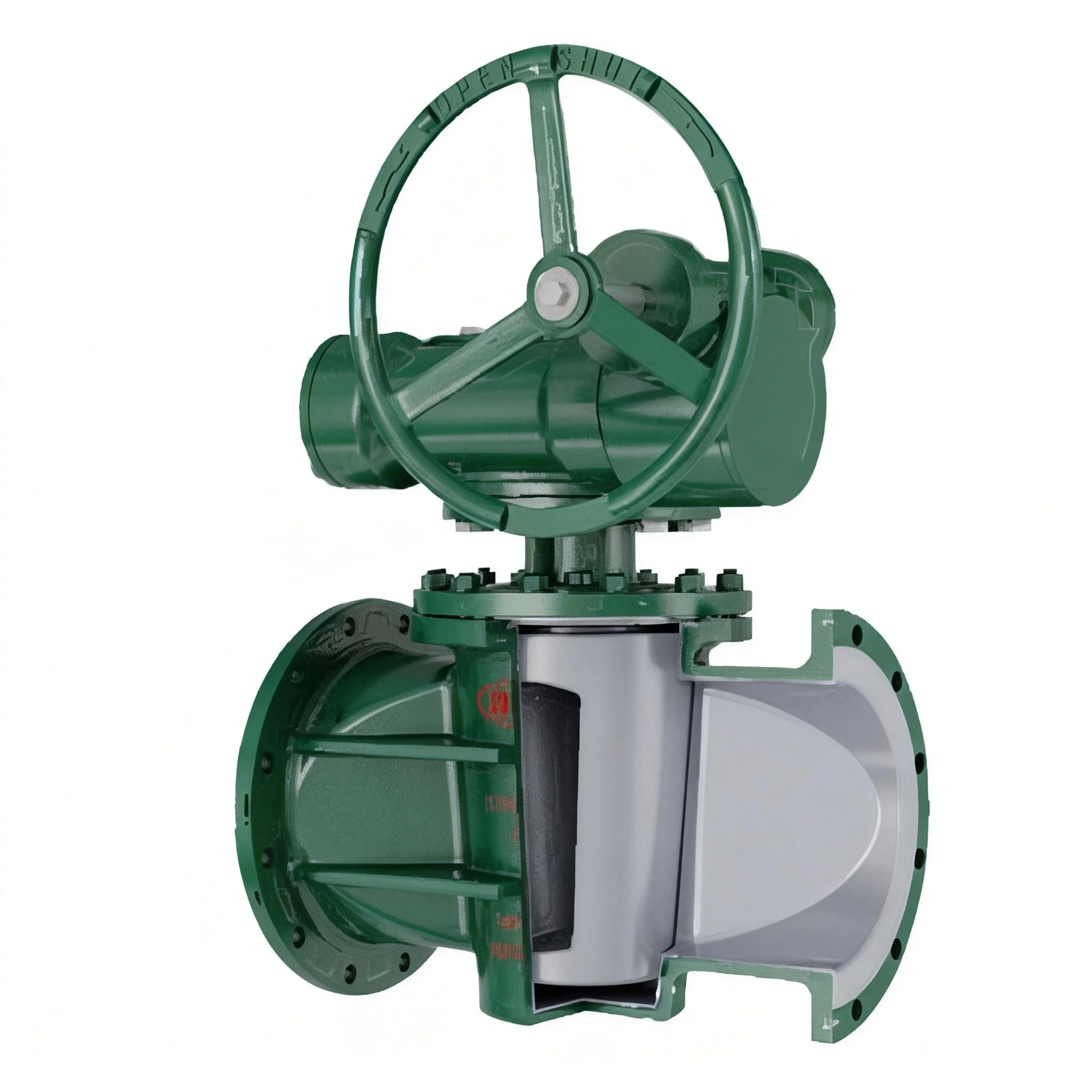
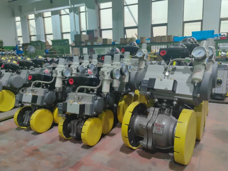
The core design of this valve lies in its full lining structure and ferrule-type connection, which effectively prevents direct contact between the corrosive medium and the metal valve body. The flange connection method ensures convenient installation and disassembly, making it suitable for integration into various pipeline systems. Depending on actual application needs, the valve can be equipped with different driving methods including manual, pneumatic, worm gear, and electric, to meet the requirements of different operation scenarios, from simple manual control to automatic intelligent control.
II. Product Features
1. Superior Corrosion Resistance
The valve adopts a full lining design, with the inner cavity of the valve body, valve cover, and other key parts lined with high-performance corrosion-resistant materials such as PTFE (F4), PFA, and FEP (F46). These lining materials have excellent resistance to almost all strong acids, strong bases, oxidants, and organic solvents, ensuring that the valve remains unaffected even when in long-term contact with highly corrosive media. The metal base material (gray cast iron, carbon steel, stainless steel, etc.) provides strong structural support, combining the advantages of high mechanical strength and strong corrosion resistance.
2. Reliable Sealing Performance
The ferrule-type structure and precision-machined plug cooperate closely with the lining/seat, forming a tight sealing pair. The adjustment shims made of enhanced PTFE (RPTFE) and O-rings made of VITON (fluoroelastomer) further enhance the sealing effect, effectively preventing medium leakage. Even under normal operating pressure and temperature ranges, the valve can maintain excellent sealing performance, ensuring the safety and stability of the pipeline system.
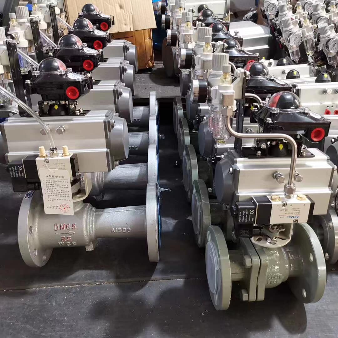
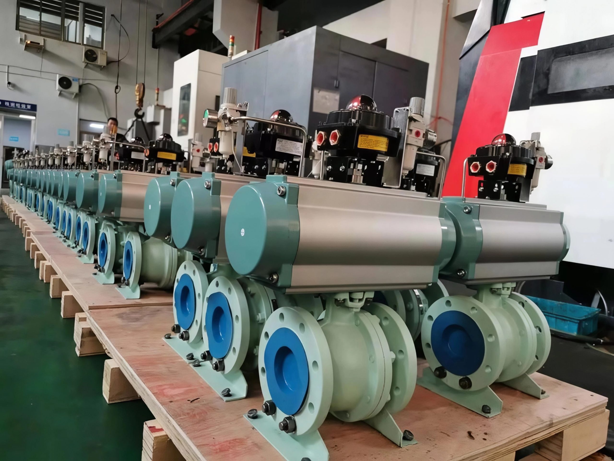
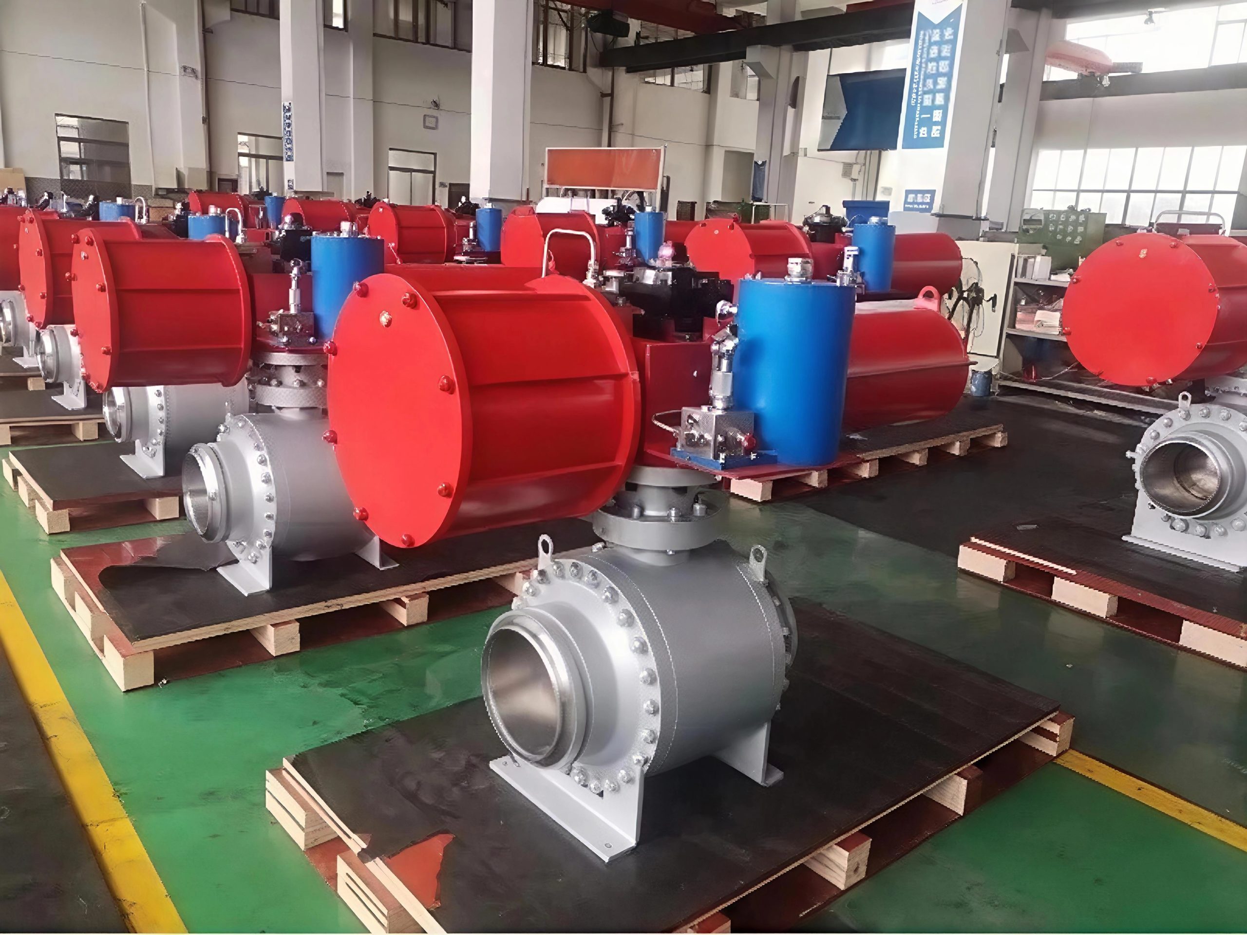
3. Wide Range of Driving Options
To adapt to different application scenarios and operation requirements, the valve offers multiple driving methods: manual, pneumatic, worm gear, and electric. Manual valves are suitable for small-caliber pipelines and scenarios requiring simple operation; pneumatic valves are ideal for automatic control systems with compressed air sources, enabling fast and efficient on-off control; worm gear-driven valves provide larger torque output, suitable for large-caliber or high-pressure working conditions; electric valves can be easily integrated into intelligent control systems, realizing remote control and precise regulation, which is convenient for centralized management of the pipeline system.
4. Stable and Durable Structure
The valve body and valve cover are made of high-quality metal materials (HT250 gray cast iron, WCB carbon steel, CF8 stainless steel, etc.), which have excellent mechanical properties and can withstand the impact of medium pressure and external loads. The full lining structure not only enhances corrosion resistance but also reduces wear between the plug and the valve body, effectively extending the service life of the valve. The product is manufactured in strict accordance with national and industry standards, ensuring consistent quality and stable performance.
5. Convenient Installation and Maintenance
The valve adopts a flanged connection design, which is consistent with universal flange standards, facilitating quick installation and disassembly with the pipeline. The internal structure is simple and reasonable, and key components such as the plug, lining, and O-ring are easy to replace. This reduces maintenance costs and downtime, improving the overall operational efficiency of the pipeline system.
III. Technical Data
1. Basic Technical Parameters
-
Nominal Pressure (PN): 0.6~1.6 MPa (fully lined)
-
Nominal Diameter (DN):15~300 mm
-
Implementation Standards:
-
Design and Manufacturing: GB/T 12240
-
Structure Length: GB/T 12221
-
Flange Size: HG/T 20592 (or as required by the contract)
-
Pressure Test: GB/T 13927
-
Symbolization: GB/T 12220
-
Filling: GB/T 12252
-
2. Valve Model and Driving Method
|
Driving Method
|
Valve Model
|
Lining Type
|
|---|---|---|
|
Manually Operated
|
X43F4
|
Full Lining (PTFE/F4)
|
|
X43PFA
|
Full Lining (PFA)
|
|
|
X43F46
|
Full Lining (FEP/F46)
|
|
|
Aerodynamic
|
X643F4
|
Full Lining (PTFE/F4)
|
|
X643PFA
|
Full Lining (PFA)
|
|
|
X643F46
|
Full Lining (FEP/F46)
|
|
|
Worm-gear Rotation
|
X343F4
|
Full Lining (PTFE/F4)
|
|
X343PFA
|
Full Lining (PFA)
|
|
|
X343F46
|
Full Lining (FEP/F46)
|
|
|
Electric Powered
|
X943F4
|
Full Lining (PTFE/F4)
|
|
X943PFA
|
Full Lining (PFA)
|
|
|
X943F46
|
Full Lining (FEP/F46)
|
3. Main Parts and Components Material Table
|
Serial Number
|
Part Name
|
Gray Cast Iron (Z)
|
Carbon Steel (C)
|
Stainless Steels (P)
|
Special Materials
|
|---|---|---|---|---|---|
|
1
|
Valve body, valve cover
|
HT250
|
WCB
|
CF8
|
–
|
|
2
|
Lining/seat
|
–
|
–
|
–
|
PTFE (F4), PFA, FEP (F46)
|
|
3
|
Stopper
|
–
|
WCB
|
–
|
–
|
|
4
|
Adjustment shims
|
–
|
–
|
–
|
RPTFE (Enhanced F4)
|
|
5
|
O-ring
|
–
|
–
|
–
|
VITON (fluoroelastomer)
|
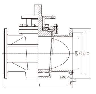
Ⅳ.The main shape and connection size


