
I. Product Introduction
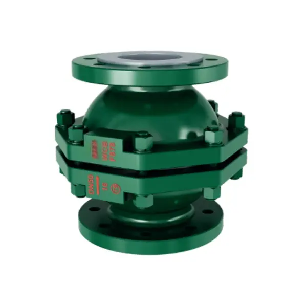
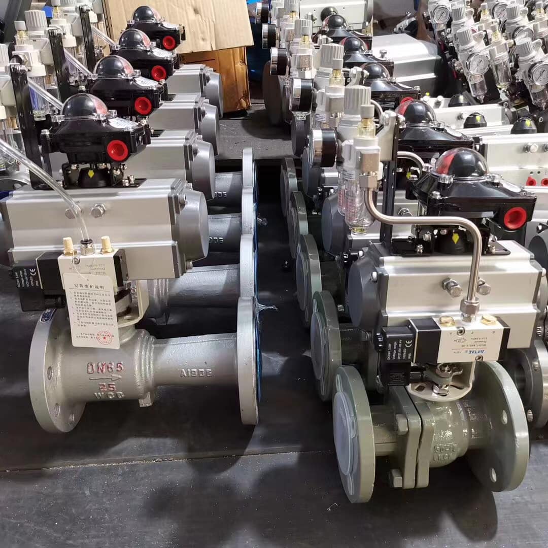
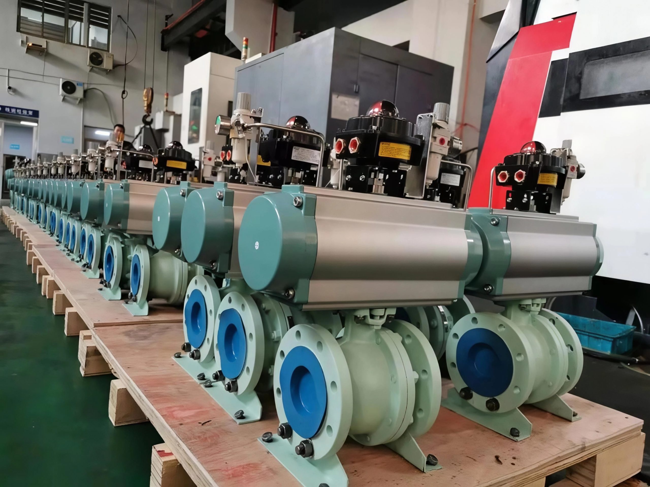
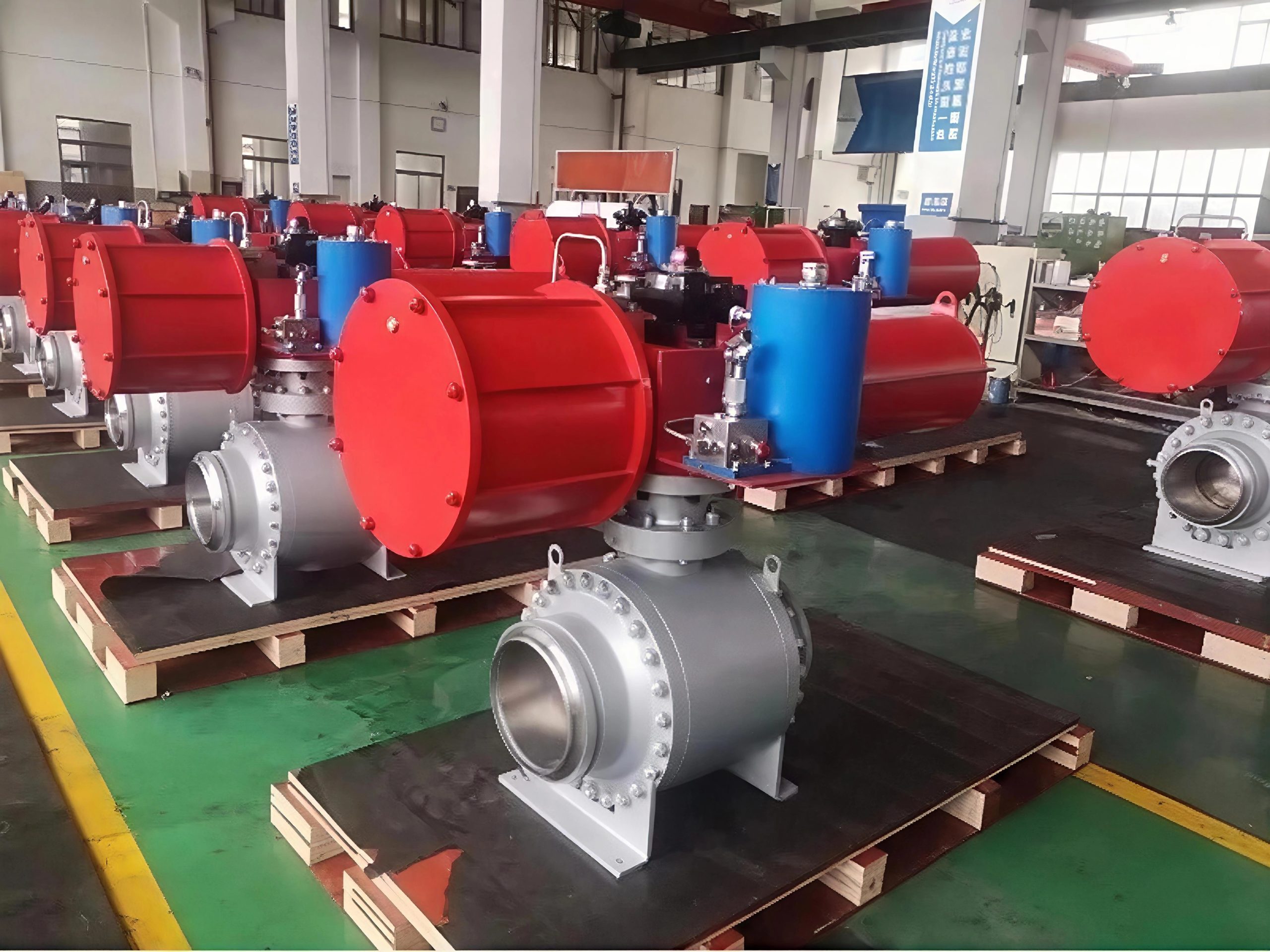
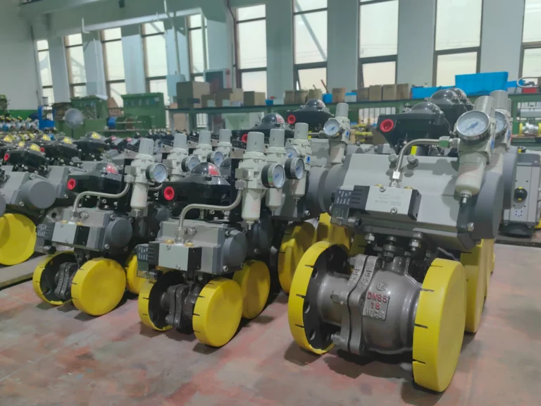
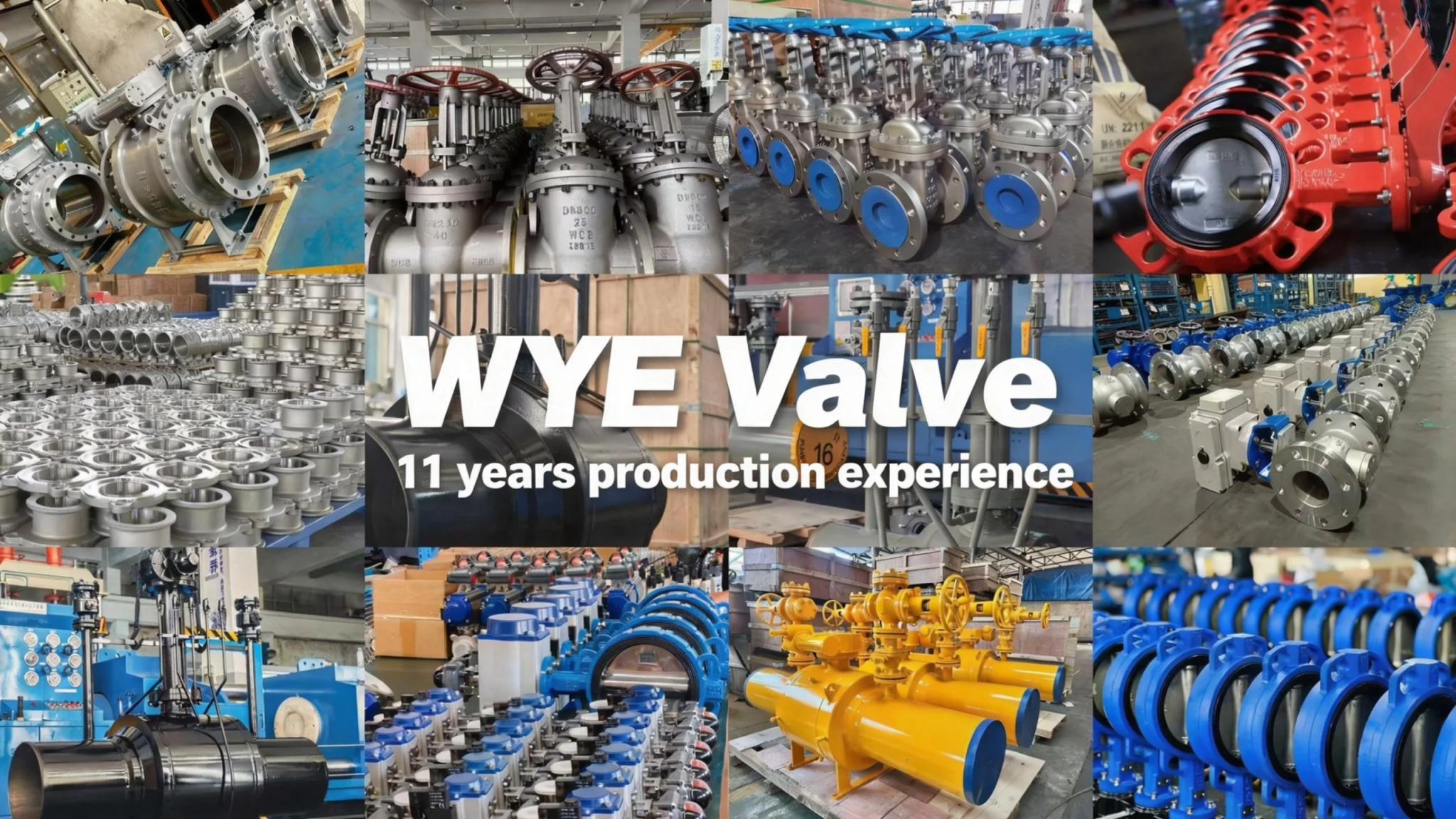
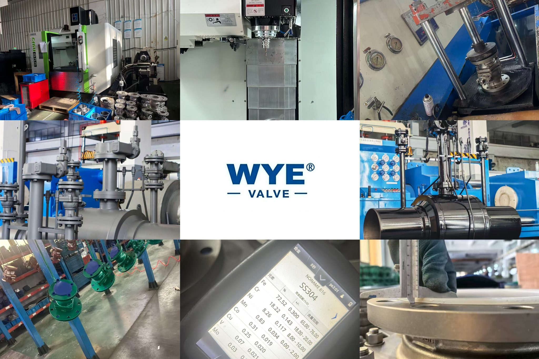
The fully lined vertical lift flange connection check valve is a high-performance automatic control valve designed for fluid pipeline systems. Its core function is to prevent the reverse flow of media in the pipeline, thereby protecting key equipment such as pumps, compressors and heat exchangers in the system, and ensuring the safe and stable operation of the entire pipeline system. The valve adopts a vertical lift structure and a full lining design, which not only has excellent sealing performance and stable flow control performance, but also can effectively resist the corrosion and wear of various harsh media, making it widely applicable to chemical, petroleum, pharmaceutical, food and beverage, water treatment and other industries with high requirements for pipeline media and operating environment.
Different from traditional check valves, this product uses a T-type flap with an integral ball structure, which optimizes the flow channel design while ensuring the check effect. It reduces the flow resistance of the medium, improves the flow capacity of the pipeline, and reduces the energy loss during the medium transportation process. The flange connection method adopted by the valve is in line with international and domestic general standards, which facilitates quick installation, disassembly and maintenance, and can be perfectly matched with various standard pipeline systems, greatly improving the versatility and interchangeability of the product.
II. Product Features
-
Excellent Corrosion Resistance: The valve adopts a full lining design, and the lining/seat can be selected from high-performance corrosion-resistant materials such as FEP (F46), PCTFE (F3), PFA (soluble polytetrafluoroethylene) and PO (polyolefin) according to the characteristics of the medium. These lining materials have excellent chemical stability and can resist the erosion of strong acids, strong alkalis, oxidants, organic solvents and other harsh media. At the same time, the main parts such as the valve body and valve cover can be made of gray cast iron, carbon steel, stainless steel or ultra-low carbon stainless steel, which further enhances the overall corrosion resistance of the valve and extends the service life in harsh working conditions.
-
Stable and Reliable Check Performance: The product adopts a new type of vertical lift structure, and the flap adopts a T-type with integral ball structure. This special structural design enables the flap to quickly respond to changes in medium flow direction. When the medium flows forward, the flap is smoothly lifted under the action of medium pressure to open the valve; when the medium tends to reverse flow, the flap quickly falls back under the combined action of its own weight and reverse medium pressure to tightly seal the valve seat, effectively preventing medium backflow. The check action is sensitive, without delay or jamming, ensuring the stability and reliability of the pipeline system.
-
Low Flow Resistance and High Flow Capacity: The internal flow channel of the valve is designed with optimization, which has the characteristics of smoothness and low resistance. The T-type flap with integral ball structure can minimize the obstruction to the medium flow when the valve is fully open, reducing the pressure loss of the medium in the pipeline. This not only improves the transportation efficiency of the medium, but also reduces the energy consumption of related equipment such as pumps, achieving energy-saving effects.
-
Convenient Installation and Maintenance: The valve adopts flange connection, which is in line with the HG/T 20592 standard (or can be customized according to the contract requirements). The connection method is simple and reliable, which is convenient for on-site installation and disassembly. At the same time, the structural design of the valve is reasonable, the internal parts are easy to disassemble and assemble, and the maintenance and replacement of vulnerable parts such as the lining and flap can be completed quickly, reducing the maintenance cost and downtime of the equipment.
-
Wide Application Range: The nominal pressure of the valve is 0.6~1.6MPa, and the nominal diameter is 25~200mm. It can meet the needs of different pipeline systems. At the same time, a variety of material combinations are available for selection, which can be customized according to the specific medium (such as strong acid, strong alkali, high-temperature medium, etc.) and operating conditions of the user. It is widely used in chemical, petroleum, pharmaceutical, food, textile, printing and dyeing, water treatment and other industries.
-
Strict Compliance with Standards: The design and manufacture of the valve strictly comply with GB/T 12224 standard, the structure length complies with the enterprise standard Q/NFL-06-88, the pressure test complies with GB/T 13927 standard, and the marking complies with GB/T 12220 standard. The strict implementation of the standards ensures the quality and performance of the product, and makes the product have good compatibility and interchangeability in the market.
III. Technical Data
1. Basic Technical Parameters
-
Nominal pressure: PN0.6~1.6 (MPa)
-
Nominal diameter: DN25~200 (mm)
-
Basic structure form: Lifting vertical (new type)
-
Basic Model: H40F3, H40F46
-
Main parts structure: Flap of the T-type with the ball with the whole ball structure
2. Implementation Standards
-
Design and Manufacturing: GB/T 12224
-
Structure length: (Enterprise Standard) Q/NFL-06-88
-
Flange Size: HG/T 20592 (or as required by the contract)
-
Pressure test: GB/T 13927
-
Symbolize: GB/T 12220
3. Main Parts and Components Material Table
|
Serial Number
|
Part Name
|
Gray Cast Iron (Z)
|
Carbon Steel (C)
|
Stainless Steels (P)
|
Stainless Steels (R)
|
Ultra-low Carbon Stainless Steel (PL)
|
Ultra-low Carbon Stainless Steel (RL)
|
|---|---|---|---|---|---|---|---|
|
1
|
Valve body, valve cover
|
HT250
|
WCB
|
CF8
|
CF8M
|
CF3
|
CF3M
|
|
2
|
Lining/seat
|
FEP (F46), PCTFE (F3), PFA (solubility polytetrafluoroethylene), PO (polyolefin)
|
|||||
|
3
|
Shaft, Flap (Plate)
|
1Cr13/35
|
WCB
|
1Cr18Ni9/CF8
|
1Cr18Ni9/CF8
|
00Cr17Ni14Mo2/CF3M
|
00Cr17Ni14Mo2/CF3M
|
|
4
|
Bolt (male component of nut and bolt)
|
35
|
35
|
1Cr17Ni2
|
1Cr17Ni2
|
1Cr18Ni9Ti
|
1Cr18Ni9Ti
|
|
5
|
Nut (female component of nut and bolt)
|
45
|
45
|
0Cr18Ni9
|
0Cr18Ni9
|
0Cr18Ni9
|
0Cr18Ni9
|
Ⅳ.The main shape and connection size
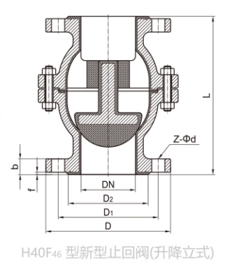
| Nominal diameter
DN(mm) |
Standard value (unit: mm) | reference point | ||||||
| L | D | D1 | D₂ | f | b | Z-Φd | W(kg) | |
| PN0.6(MPa) | ||||||||
| 25 | 160 | 100 | 75 | 60 | 3.5 | 14 | 4-Φ11 | 6 |
| 32 | 160 | 120 | 90 | 70 | 3.5 | 14 | 4-Φ14 | 8 |
| 40 | 186 | 130 | 100 | 80 | 3.5 | 14 | 4-Φ14 | 10 |
| 50 | 186 | 140 | 110 | 90 | 4 | 14 | 4-Φ14 | 14 |
| 65 | 198 | 160 | 130 | 110 | 4 | 14 | 4-Φ14 | 18 |
| 80 | 215 | 190 | 150 | 128 | 4 | 16 | 4-Φ18 | 21 |
| 100 | 267 | 210 | 170 | 148 | 4.5 | 16 | 4-Φ18 | 40 |
| 125 | 310 | 240 | 200 | 178 | 4.5 | 18 | 8-Φ18 | 70 |
| 150 | 394 | 265 | 225 | 202 | 4.5 | 18 | 8-Φ18 | 90 |
| 200 | 457 | 320 | 280 | 258 | 4.5 | 20 | 8-Φ18 | 120 |
| PN1.0(MPa) | ||||||||
| 25 | 160 | 115 | 85 | 68 | 3.5 | 18 | 4-Φ14 | 6.8 |
| 32 | 160 | 140 | 100 | 78 | 3.5 | 18 | 4-Φ18 | 10 |
| 40 | 186 | 150 | 110 | 88 | 3.5 | 18 | 4-Φ18 | 11.5 |
| 50 | 186 | 165 | 125 | 102 | 4 | 18 | 4-Φ18 | 15 |
| 65 | 198 | 185 | 145 | 122 | 4 | 18 | 8-Φ18 | 20 |
| 80 | 215 | 200 | 160 | 138 | 4 | 20 | 8-Φ18 | 23 |
| 100 | 267 | 220 | 180 | 158 | 4.5 | 20 | 8-Φ18 | 44 |
| 150 | 394 | 285 | 240 | 212 | 4.5 | 22 | 8-Φ22 | 95 |
| 200 | 457 | 340 | 295 | 268 | 4.5 | 24 | 8-Φ22 | 120 |


