501L Top-Guided Multi-Hole Cage Control Valve
Stable Process Control for High Differential Pressure and Low-Noise Applications
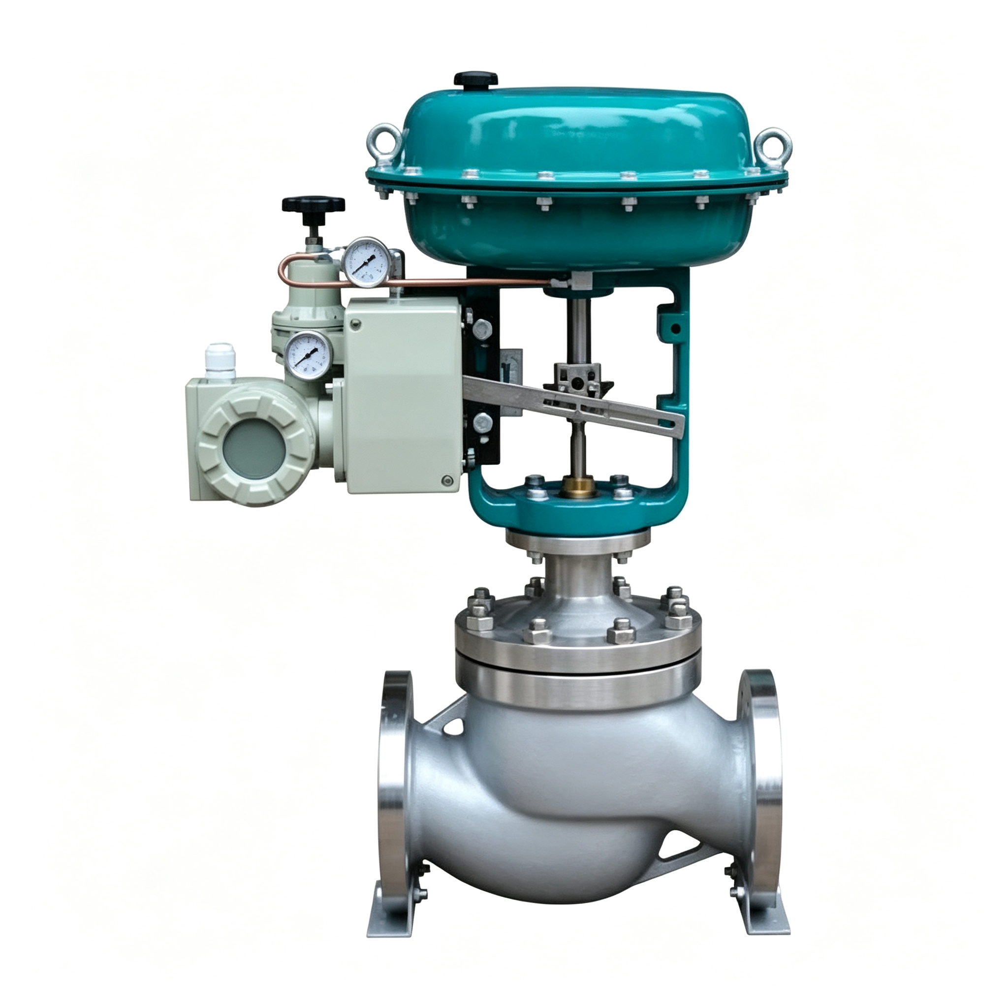
The Wye 501L Top-Guided Multi-Hole Cage Control Valve is designed for industrial applications requiring stable flow regulation, high differential pressure capability and low-noise performance.
Featuring a sleeve-guided, pressure-balanced valve plug, the 501L combines stable dynamic performance with precise flow control.
Its multi-hole cage structure helps manage fluid velocity and pressure reduction, making it suitable for demanding process conditions where noise, vibration and valve stability are important.
DN25–DN300 | PN1.6–PN32.0 MPa | Class 150–900
Temperature Options: -196°C to +550°C
[Request a Quote] [Send Your Operating Conditions]
一、Product Overview
1.1 What Is the 501L Control Valve?
The 501L is a top-guided, multi-hole cage control valve featuring a pressure-balanced valve plug.
Its internal structure combines sleeve guidance with a balanced trim design to provide stable operation under demanding industrial process conditions.
The multi-hole cage allows the valve to manage fluid flow through multiple passages, helping reduce fluid velocity and improve control stability.
1.2 What Problems Can the 501L Help Solve?
High differential pressure and demanding process conditions can create several challenges for industrial control valves.
Common problems include:
- High fluid velocity
- Excessive flow noise
- Unstable valve plug movement
- High differential pressure
- Increased actuator thrust requirements
- Valve trim wear
- Difficult flow regulation
The 501L combines a pressure-balanced trim with different cage configurations to address these requirements.
二、Process Control Solutions
2.1 High Differential Pressure Control
Large pressure differences across a control valve can generate significant fluid forces.
The 501L uses a pressure-balanced valve plug to reduce the unbalanced force acting on the trim.
This design helps the valve operate under higher differential-pressure conditions while reducing the actuator thrust required for valve movement.
Customer Benefits
- Reduced unbalanced forces
- Lower actuator thrust requirements
- Improved valve operating stability
- Configuration for high differential-pressure applications
2.2 Low-Noise Flow Control
High fluid velocity through a control valve can generate excessive noise and create demanding operating conditions.
The 501L multi-hole cage structure distributes the flow through multiple passages.
This arrangement helps manage fluid velocity and reduce noise associated with pressure reduction.
Customer Benefits
- Better fluid velocity management
- Reduced flow-generated noise
- Improved process control stability
- Configuration for demanding pressure-drop conditions
2.3 Stable Flow Regulation
The cage-guided structure provides support for the valve plug throughout its travel.
Combined with the pressure-balanced design, it helps maintain stable operation during flow regulation.
The valve can be configured with equal-percentage or linear flow characteristics according to the required control duty.
三、Valve Structure and Trim Options
3.1 Pressure-Balanced Cage Structure
The 501L features a pressure-balanced cage-guided design.
The balanced trim helps reduce fluid forces acting on the valve plug, allowing the valve to operate with lower actuator thrust under suitable conditions.
3.2 Cage-Type Sleeve Structure
The cage-type sleeve configuration is intended for applications involving relatively clean media.
The catalogue describes this configuration as suitable for medium and large pressure conditions, with higher requirements for media cleanliness.
3.3 Single-Stage Cage Structure
The single-stage cage structure is designed for high-temperature and high-pressure applications.
According to the catalogue, it is suitable for operating pressures below PN16.0 MPa and applications with higher media requirements.
3.4 Two-Stage Cage Structure
The two-stage cage structure is designed for demanding pressure-reduction applications.
The catalogue describes this configuration as suitable for operating pressures below PN32.0 MPa, particularly where the differential pressure is relatively large.
By distributing pressure reduction across two stages, the design helps manage demanding flow conditions.
四、Temperature and Media Options
4.1 High-Temperature Configuration
The 501L can be supplied with a high-temperature configuration for applications involving:
- Steam
- Hot oil
- Other high-temperature process fluids
Catalogue Temperature Range: +250°C to +550°C
4.2 Low-Temperature Configuration
Low-temperature configurations are available for applications involving:
- Liquid nitrogen
- Low-temperature process fluids
- Cryogenic service
Catalogue Temperature Range: -70°C to -196°C
4.3 Bellows Seal Configuration
A bellows-type configuration is available for applications involving:
- Flammable gases
- Explosive gases
- Toxic fluids
- Corrosive media
The appropriate sealing arrangement should be selected according to the actual process medium, pressure and temperature.
五、Technical Specifications
5.1 Main Technical Parameters
| Parameter | 501L Specification |
|---|---|
| Model | 501L |
| Valve Type | Top-Guided Multi-Hole Cage Control Valve |
| Body Form | Straight-through S-type cast body |
| Trim | Pressure-balanced multi-hole cage |
| Nominal Size | DN25–DN300 |
| NPS | 1″–12″ |
| Nominal Pressure | PN1.6–PN32.0 MPa |
| ASME Pressure Class | Class 150–900 |
| Temperature Range | -196°C to +550°C, depending on configuration |
| End Connection | Flanged, welded or threaded |
| Face-to-Face Standard | IEC 60534 |
| Packing | PTFE or flexible graphite |
| Gasket | Metal/graphite wound gasket |
| Actuation | Pneumatic or electric |
| Flow Characteristics | Equal percentage or linear |
| Adjustable Range | 50:1 |
| Rated Cv | 10–1400 (equal percentage); 11–1500 (linear) |
| Allowable Leakage | Metal seat: Class IV; soft seat: Class VI |
Actual pressure, temperature and leakage performance depend on the selected valve configuration.
六、Body and Trim Materials
6.1 Body Materials
The 501L is available with carbon steel and stainless steel body configurations.
Carbon Steel
- WCB
- LCB
- WC9
Stainless Steel
- CF8
- CF8M
- CF3M
6.2 Trim Materials
Trim material options include:
- 304 stainless steel
- 316 stainless steel
- 316L stainless steel
The valve cage, plug and stem materials are selected according to the body configuration and operating conditions.
6.3 Packing and Sealing Materials
Available materials include:
- PTFE
- Flexible graphite
- Metal/graphite wound gaskets
Special material configurations can be considered according to the customer’s process requirements.
七、Actuator Options
7.1 Pneumatic Actuator
The 501L can be supplied with a pneumatic diaphragm actuator for regulating and switching applications.
The catalogue lists multi-spring pneumatic actuator configurations with different spring ranges.
When equipped with a valve positioner, the actuator supports a 4–20 mA DC control signal.
Air-to-close and air-to-open configurations are available.
7.2 Electric Actuator
Electric actuator configurations are available for automatic flow and pressure regulation.
The catalogue includes intelligent integrated electric actuator options with 4–20 mA DC control input.
7.3 Optional Accessories
Depending on the actuator configuration, optional accessories include:
- Valve positioner
- Handwheel
- Solenoid valve
- Travel switch
- Position valve
- Heater
The final actuator and accessory combination should be selected according to the valve size, operating differential pressure and required control function.
八、Why Choose the Wye 501L?
8.1 Pressure-Balanced Trim
The pressure-balanced valve plug helps reduce unbalanced forces and actuator thrust requirements.
8.2 Multi-Hole Cage Design
The multi-hole cage helps manage fluid velocity and pressure reduction.
8.3 Multiple Trim Configurations
Different cage structures can be selected according to differential pressure, operating conditions and media requirements.
8.4 Wide Temperature Options
High-temperature, low-temperature and bellows configurations are available for different process requirements.
8.5 Application-Based Valve Selection
Valve size, Cv, trim structure, materials and actuator can be configured according to the customer’s operating conditions.
九、Valve Selection Information
9.1 Information Required for Selection
Please provide the following process data:
- Process medium
- Inlet pressure
- Outlet pressure
- Differential pressure
- Minimum flow rate
- Normal flow rate
- Maximum flow rate
- Operating temperature
- Pipe size
- Required Cv, if available
- Body material requirements
- Trim material requirements
- Pneumatic or electric actuator
- Required control signal
- Shutoff requirements
9.2 Application-Based Configuration
Based on the supplied operating data, the appropriate valve size, trim structure, Cv, material combination and actuator can be determined.
十、Send Us Your Operating Conditions
High differential-pressure applications require careful consideration of valve trim design, flow characteristics and actuator selection.
Send us your operating conditions to discuss a suitable 501L configuration for your process.
[Request Valve Selection]
[Request a Quote]
[Download Datasheet]
[Contact an Engineer]