
一.Product Introduction
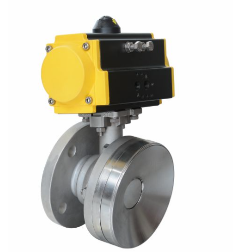
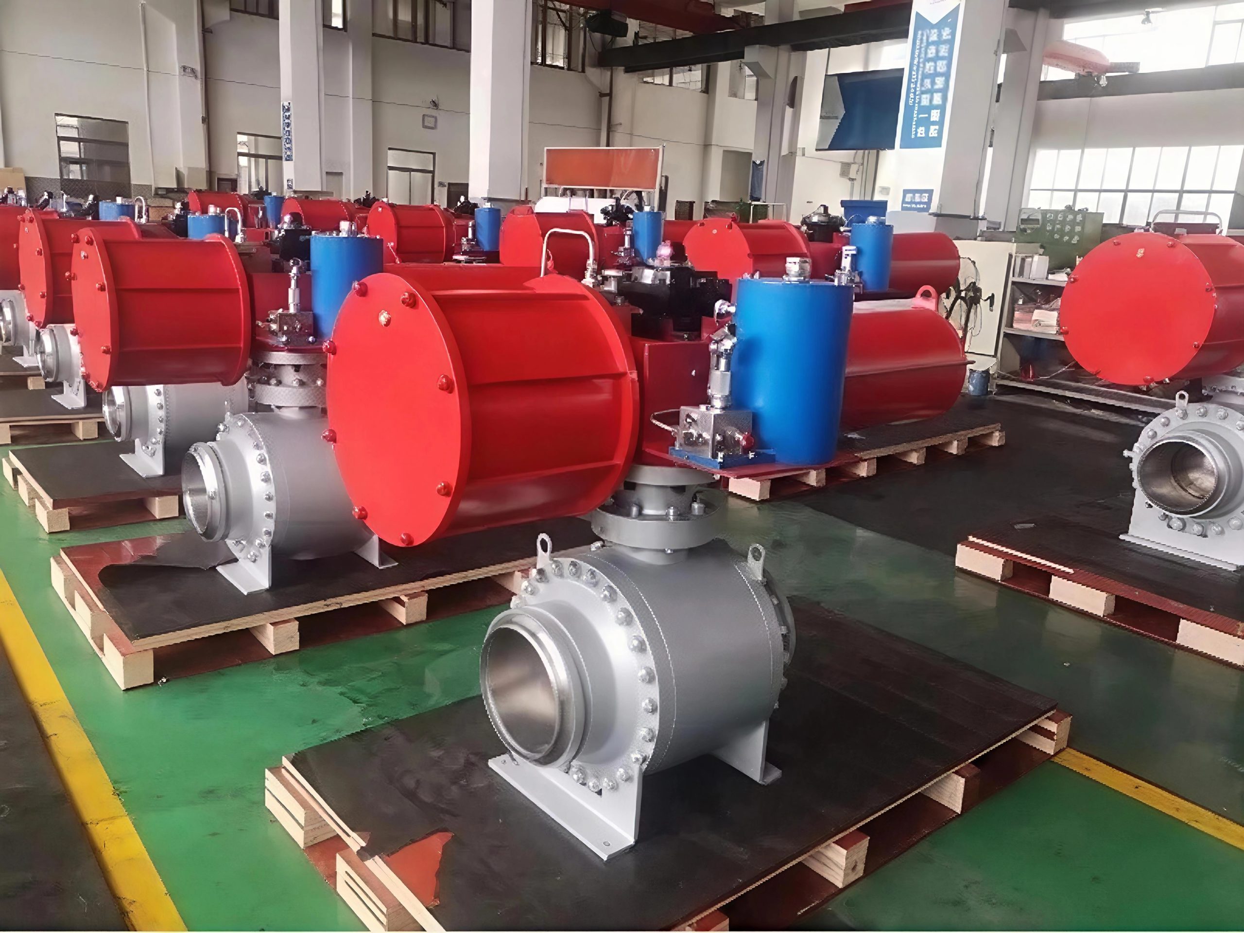
The Tank bottom discharge valve is a specialized fluid control device designed for the discharge system at the bottom of storage tanks. It features a compact and rational structural design, enabling convenient installation. Its valve core (disc) can fit flush with the tank bottom surface — when the valve is closed, no material remains in the valve chamber, effectively avoiding material accumulation and contamination.
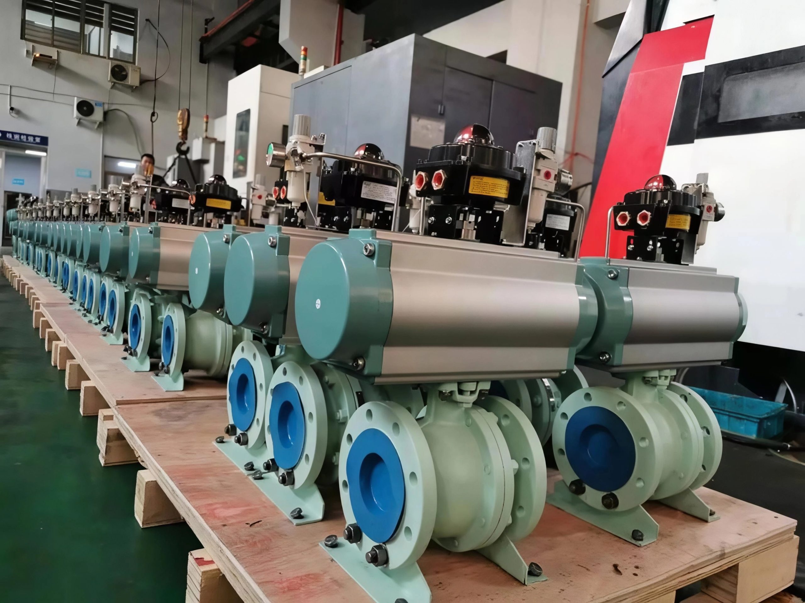
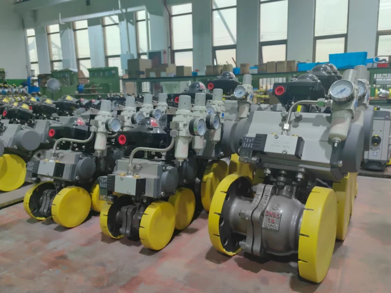
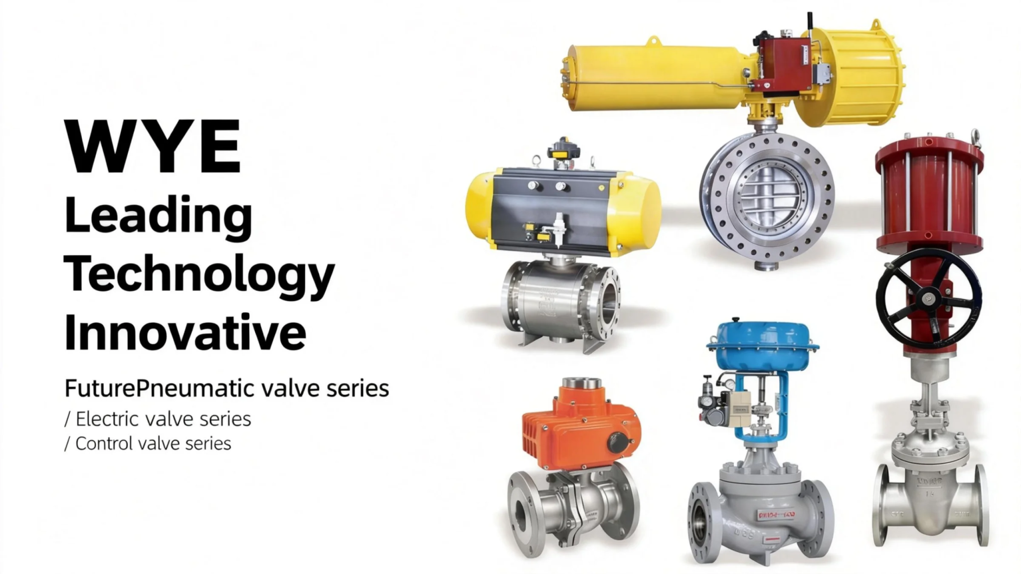
It adopts reliable internal and external sealing structures to adapt to tank discharge working conditions. The external valve stem uses an angled design: it adjusts the valve stem from a vertical to an inclined position (relative to the tank bottom), making it easy to install actuators (such as the pneumatic actuator in the diagram). This valve is especially suitable for controlling bottom media discharge in pharmaceutical, chemical, food, and petroleum production tanks.
二.Product Features
- Compact & easy to install: The integrated structural design simplifies on-site assembly, reducing installation effort.
- No material residue: The valve core fits flush with the tank bottom, eliminating material accumulation in the valve chamber when closed — ideal for clean production scenarios.
- Reliable sealing performance: Equipped with effective internal and external sealing structures, it stably adapts to the pressure and media characteristics of tank bottom discharge.
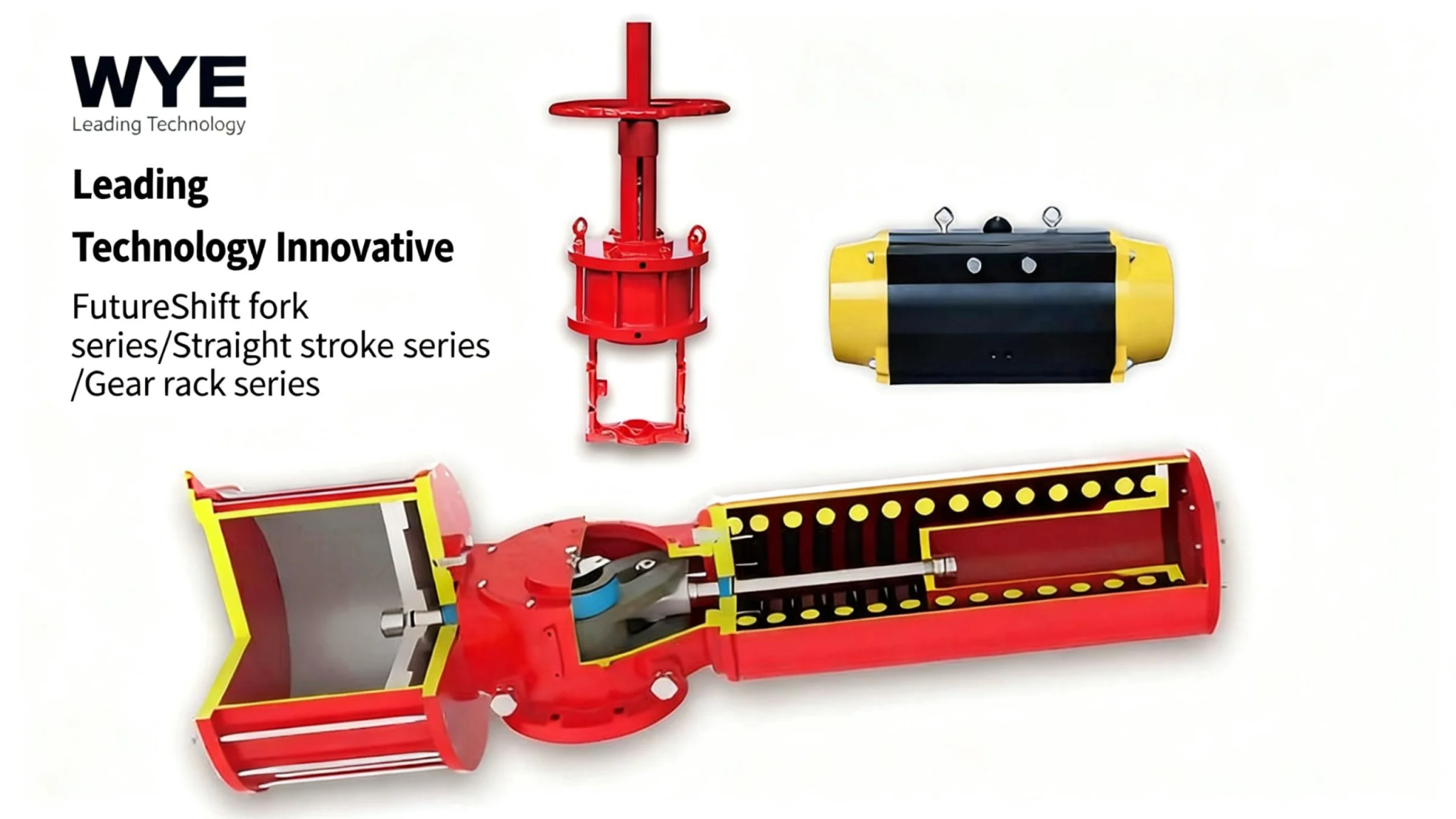
- Actuator-friendly design: The angled valve stem avoids spatial conflicts with the tank body, facilitating the matching and installation of pneumatic/electric actuators.
- Broad application scope: Suitable for bottom discharge of storage tanks in pharmaceutical, chemical, food, petroleum and other industries.
三.Technical data
1. Executive Standards
| Item | GB Standard |
|---|---|
| Design basis | GB/T12237 |
| Structure length (flange connection) | GB/T12221 |
| Connecting flange size | GB/T9113, JB/T79, HG/T20592-2009 |
| Testing and Inspection | GB/T13927, JB/T7902 |
| Note: Structural length and connecting flange size can be customized per user requirements. |
2. List of Main Parts and Materials
| Serial No. | Part Name | Material Quality (C) | Material Quality (P) | Material Quality (R) |
|---|---|---|---|---|
| 1 | Valve Body | WCB | 1Cr18Ni9Ti | 1Cr18Ni12Mo2Ti |
| 2 | Nut | 35 | 1Cr18Ni9Ti | 1Cr18Ni9Ti |
| 3 | Gasket | PTFE/Graphite metal pad | Graphite metal pad | 1Cr18Ni9Ti |
| 4 | Bolt | 35 | 1Cr18Ni9Ti | 1Cr18Ni9Ti |
| 5 | Valve Body | WCB | 1Cr18Ni9Ti | 1Cr18Ni9Ti |
| 6 | Valve Seat | PTFE/Nylon | PPL/Nylon | PPL |
| 7 | Ball | 1Cr13 | 1Cr18Ni9Ti | 1Cr18Ni12Mo2Ti |
| 8 | Valve Stem | 1Cr13 | 1Cr18Ni9Ti | 1Cr18Ni12Mo2Ti |
| 9 | Shim | 1Cr18Ni9Ti | 1Cr18Ni9Ti | 1Cr18Ni12Mo2Ti |
| 10 | Filler | PTFE | PTFE/Flexible graphite | Flexible graphite |
| 11 | Filler Gland | WCB | 1Cr18Ni9Ti | 1Cr18Ni9Ti |
| 12 | Gland Bush | PTFE Composite bearing | PTFE Composite bearing | – |
| 13 | Bolt | 35 | 1Cr18Ni9Ti | 1Cr18Ni9Ti |
| 14 | Gland Bolt | 35 | 1Cr18Ni9Ti | 1Cr18Ni9Ti |
| 15 | Connecting Seat | 1Cr18Ni9Ti | 1Cr18Ni9Ti | 1Cr18Ni9Ti |
| 16 | Bolt | 35 | 1Cr18Ni9Ti | 1Cr18Ni9Ti |
| 17 | Connecting Sleeve | 35 | 1Cr18Ni9Ti | 1Cr18Ni9Ti |
| 18 | Pneumatics Seals | AT/AW Series | AT/AW Series | – |
| 19 | Position Indicator | Plastics | Plastics | – |
3. Options for Attachments
- Control components: Solenoid valve
- Auxiliary control parts: Single solenoid valve, double solenoid valve, limit switch feedback device
- Adjustable accessories: Electric positioner, pneumatic positioner, electrical converter
- Pneumatic accessories: SD air filter, inflation pressure reducing valve, air source treatment triplet
- Manual mechanism: SD manual device
四.The main shape and connection size
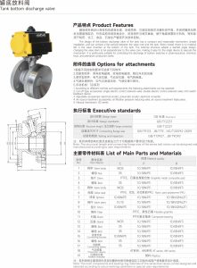


