
I. Product Introduction
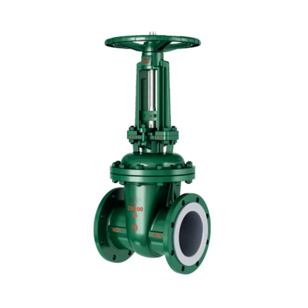
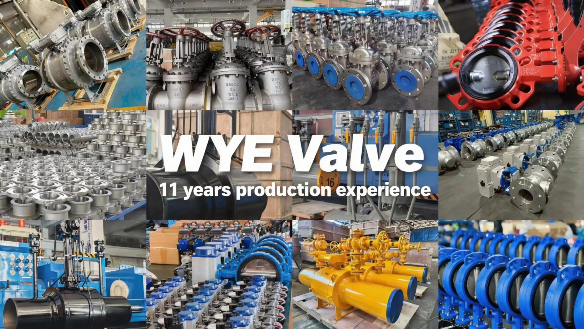
The Wedge Gate Valve with Flange Connection is a crucial component widely applied in various industrial pipeline systems, designed for on-off control of medium flow. Characterized by its flange connection mode, this valve enables convenient and secure installation and disassembly, ensuring tight sealing and reliable operation even in harsh working conditions. It is suitable for media such as water, steam, oil, corrosive chemicals, and other fluids, covering a broad range of industries including petroleum, chemical, water treatment, power generation, metallurgy, and municipal engineering.
This series of wedge gate valves adopts a wedge-shaped gate design, which can achieve effective sealing through the tight fit between the gate and the valve seat. The fully lined structure option (as reflected in the basic models) further enhances the valve’s corrosion resistance, making it applicable to pipelines transporting strong corrosive media. With multiple operation modes (manual, worm gear, pneumatic, electric) available, it can meet the diverse needs of different application scenarios, from simple manual control to automatic control in large-scale industrial systems.
II. Product Features
-
Reliable Sealing Performance: The wedge-shaped gate design ensures good centering performance and tight contact with the valve seat. Combined with high-quality lining materials (such as PTFE, PVDF, etc.), it achieves excellent sealing effect, effectively preventing medium leakage and ensuring the safety and stability of the pipeline system.
-
Convenient Flange Connection: Adopting standard flange sizes (compliant with HG/T 20592/ASME B16.5 or customized according to contract requirements), it is compatible with most industrial pipelines, facilitating quick installation, maintenance, and replacement, reducing the difficulty and cost of on-site construction.
-
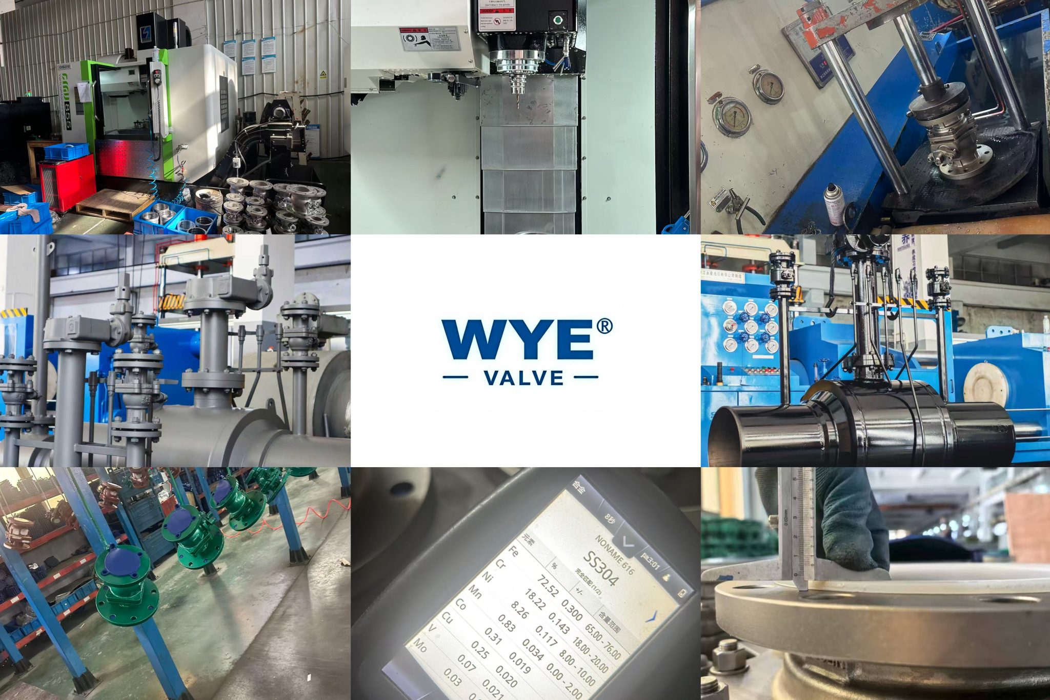
Excellent Corrosion Resistance: For fully lined models, the valve body internal and valve seat are lined with high-performance corrosion-resistant materials (PCTFE, PVDF, FEP, PFA, PO, etc.). The main components can also be made of stainless steel (CF8, CF8M) and other corrosion-resistant materials, enabling the valve to adapt to various corrosive media and extending its service life in harsh environments.
-
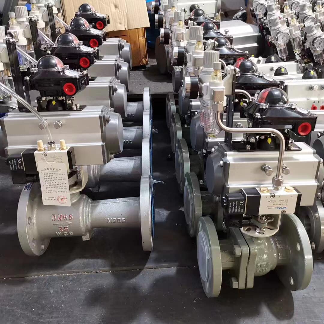
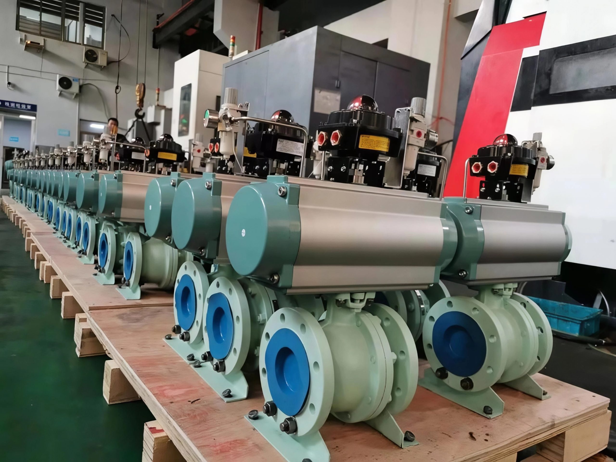
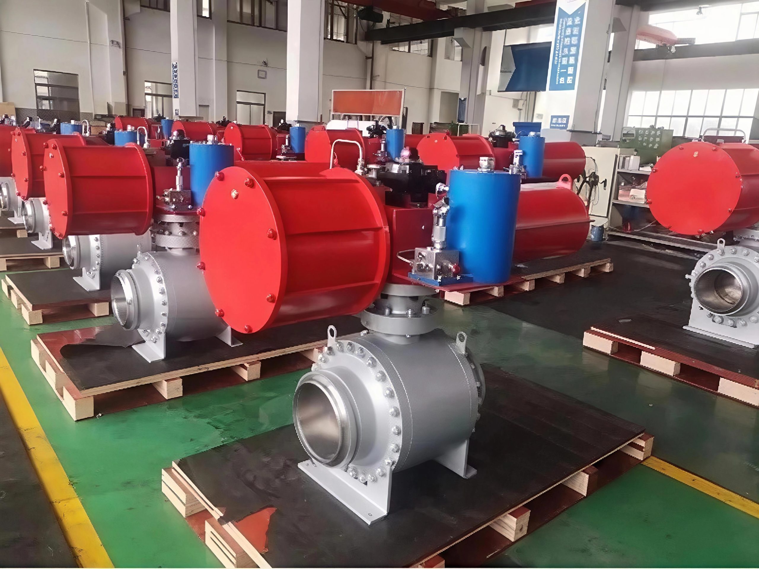
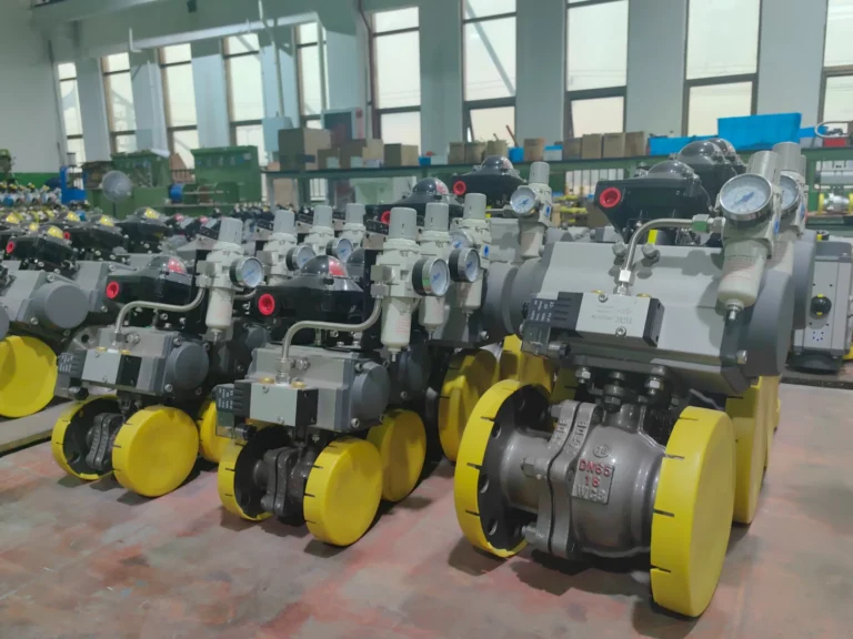
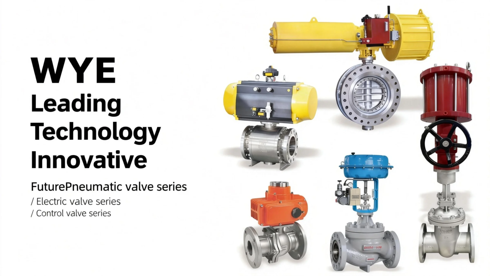
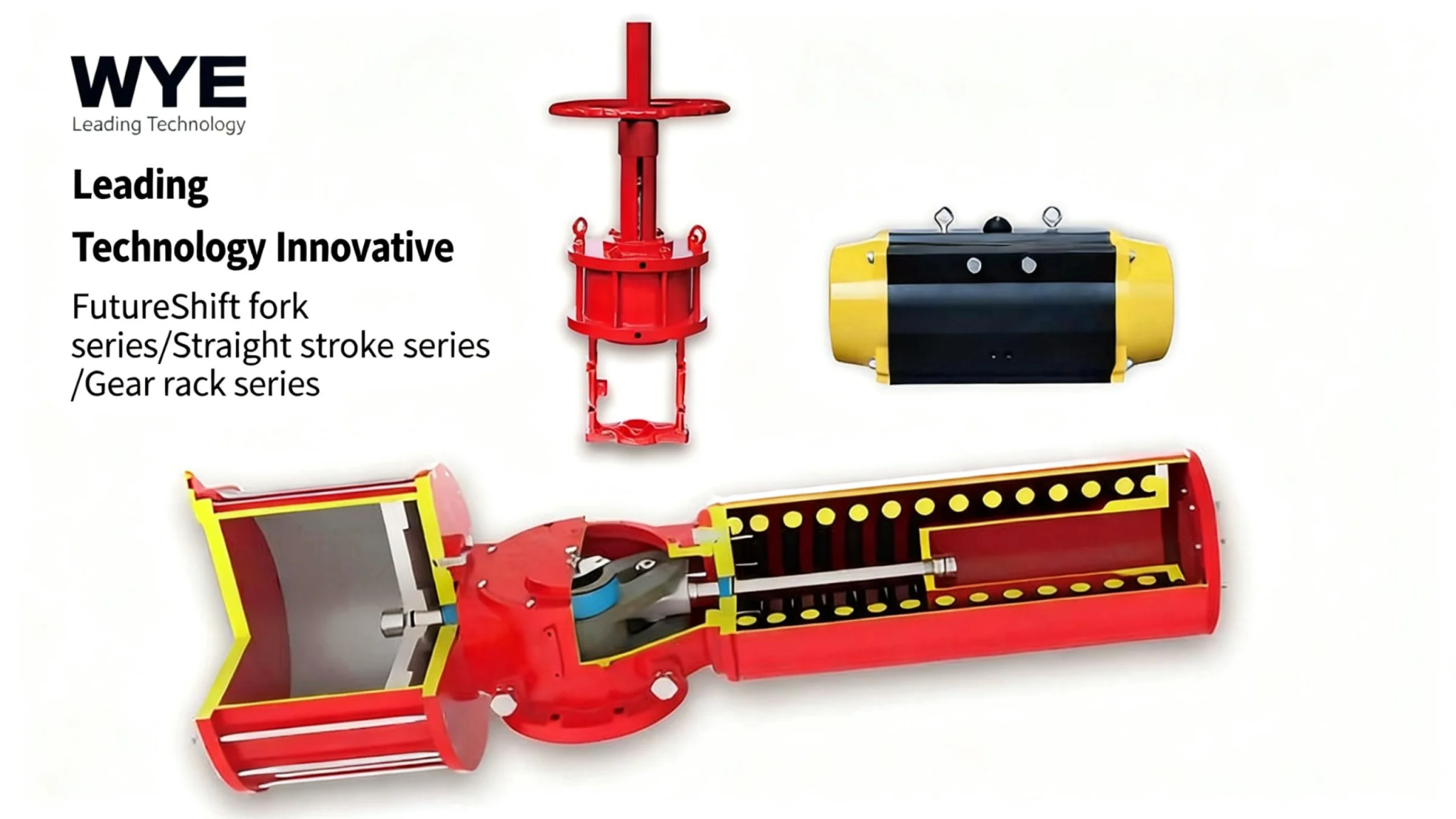
Diverse Operation Modes: Providing manual, worm gear, pneumatic, and electric operation options to meet the needs of different working conditions. Electric and pneumatic modes are suitable for remote control and automatic control systems, improving the efficiency of pipeline operation and reducing manual intervention; worm gear mode enhances torque, making operation more labor-saving.
-
Wide Application Range: Covering a nominal pressure range of PN0.6~1.6MPa (ANSI CL150) and a nominal diameter range of DN15~500mm (1/2″~24″), it can be matched with different pipeline specifications and adapt to various pressure and flow requirements.
-
Sturdy and Durable Structure: The valve body, bonnet, bracket, and other key components are made of high-quality materials such as gray cast iron (HT250), carbon steel (WCB), and stainless steel, which have excellent mechanical properties and pressure-bearing capacity, ensuring the valve’s stable operation under long-term use and harsh working conditions.
-
Compliance with Strict Standards: The design, manufacturing, structure length, flange size, pressure test, and marking all comply with relevant national and international standards (GB/T12234, GB/T 12221, HG/T 20592/ASME B16.5, GB/T 13927, GB/T 12220, etc.), ensuring product quality and interchangeability.
III. Technical Data
3.1 Basic Technical Parameters
-
Nominal Pressure: PN0.6~1.6 (MPa), ANSI CL150
-
Nominal Diameter: DN15~500 (mm), 1/2″~24″
3.2 Implementation Standards
-
Design and Manufacturing: GB/T12234
-
Structure Length: GB/T 12221
-
Flange Size: HG/T 20592/ASME B16.5 (or as required by the contract)
-
Pressure Test: GB/T 13927
-
Symbolize: GB/T 12220
-
Fill: GB/T 12252
3.3 Basic Model (Fully Lined)
-
Manual: Z41F4, Z41F46, Z40F4, Z40F46
-
Worm Gear Rotate: Z541F4, Z541F46
-
Pneumatic: Z641F4, Z640F, Z641F46, Z640F46
-
Electric: Z941F4, Z9B40F4, Z941F46, Z9B40F46
3.4 Main Parts and Components Material Table
|
Serial Number
|
Part Name
|
Material (Gray Cast Iron/Z)
|
Material (Carbon Steel/C)
|
Material (Stainless Steels/P/R)
|
|---|---|---|---|---|
|
1
|
Valve body, bonnet, flap
|
HT250
|
WCB
|
CF8, CF8M
|
|
2
|
Lining/seat
|
PCTFE(F3), PVDF(F4), FEP(F48), PFA(Soluble polytetrafluoroethylene), PO(polyolefin)
|
||
|
3
|
Packing, Gaskets
|
PTFE(F4)
|
||
|
4
|
Brackets
|
HT250
|
WCB
|
CF8
|
|
5
|
Handwheels
|
QT400-15
|
–
|
–
|
Ⅳ.The main shape and connection size
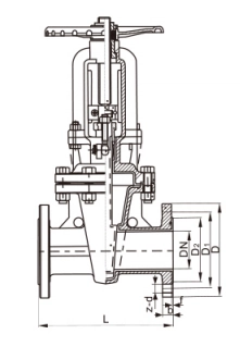
Main connection dimensions and weight
Main connection dimensions and weight
Main connection dimensions and weight
Main connection dimensions and weight


