Mobile Phone Wireless Controlled Electric Actuated Gate Valve
I. Product Overview
1.1 Wireless Remote Control for Electric Gate Valve Operation
The Mobile Phone Wireless Controlled Electric Actuated Gate Valve combines an electric actuated gate valve with wireless communication and remote control capabilities.
Through an industrial IoT network, the valve can be connected to remote monitoring and control systems, allowing operating information to be transmitted between field equipment and the monitoring platform.
The system supports multiple wireless communication methods, including WiFi, LoRa, NB-IoT, GPRS, 4G and 5G, providing flexible communication options for different field conditions.
1.2 Key Capabilities
- Wireless remote valve control
- Mobile and web-based monitoring
- Real-time data transmission
- Multiple wireless communication methods
- Cloud platform connectivity
- Equipment status monitoring
- Data acquisition and control
- ESD emergency shutdown support
- Third-party platform integration
- Renewable energy system integration
II. Remote Valve Operation
2.1 Remote Control
The wireless control system enables connected electric valve equipment to be accessed and controlled remotely through the industrial IoT network.
Remote control can be configured according to different operating conditions, helping operators manage field valve equipment without relying solely on direct on-site operation.
2.2 Mobile and Web Access
The monitoring and control architecture supports remote access through web and mobile devices.
Connected equipment information can be transmitted through the wireless network to the monitoring platform, allowing operators to access field operating information remotely.
2.3 Multiple Wireless Communication Options
According to the supplied system documentation, supported communication methods include:
- WiFi
- LoRa
- NB-IoT
- GPRS
- 4G
- 5G
The communication method can be selected according to the field network and project requirements.
III. Industrial IoT Connectivity
3.1 Connect Field Valves to the IoT Network
The electric actuated gate valve can be incorporated into an industrial IoT monitoring and control network.
Field equipment can communicate through DTU or RTU devices, allowing operating data to be transmitted between valves, instruments, the communication network and the cloud platform.
3.2 Data Acquisition and Transmission
The IoT system supports data collection and control of different types of instruments and valves.
Available functions include:
- Wireless data transmission
- Data acquisition
- Valve control
- Switching control
- Equipment status monitoring
- Continuous data upload
- Connection to multiple devices
3.3 Third-Party System Integration
The system supports integration with third-party data platforms and control systems.
This allows the wireless valve control solution to be incorporated into a broader monitoring or automation system according to project requirements.
IV. Real-Time Monitoring
4.1 Monitor Key Operating Parameters
According to the connected instruments and system configuration, the industrial IoT system can monitor key field parameters in real time.
Monitoring parameters shown in the supplied documentation include:
- Valve position
- Pressure
- Temperature
- Flow rate
- Water level
- Battery status
- Operating records
- Fault logs
4.2 Valve and Instrument Monitoring
The system can collect information not only from the valve but also from connected field instruments.
This allows valve operation and related process parameters to be monitored through the same IoT system.
4.3 Operating and Fault Records
Operating records and fault logs can be transmitted to the platform for centralized management.
The system also supports historical data queries and report generation for stored operating information.
V. Wireless Control Architecture
5.1 System Architecture
The wireless valve monitoring and control system connects field equipment with remote monitoring devices through the communication network.
A typical system architecture can be represented as:
Electric Actuated Gate Valve → DTU / RTU → Wireless Network → Cloud Platform → Web / Mobile Monitoring
5.2 4G DTU
The 4G DTU provides wireless data transmission between field equipment and the communication network.
The DTU can be used to upload collected data to the cloud platform.
5.3 4G RTU
The 4G RTU supports:
- Wireless communication
- Data acquisition
- Control
- Switching
This enables the RTU to perform both data collection and control functions within the field system.
5.4 LoRa DTU
The LoRa DTU provides wireless data transmission through a LoRa communication network.
It can be used as part of the field communication architecture according to the required network configuration.
5.5 Multiple Network Configurations
The system supports different network configurations and can combine communication methods according to field requirements.
The supplied system diagram shows configurations including 4G DTU, 4G RTU, LoRa DTU and 4G-to-LoRa communication, with support for 4G/5G network access.
VI. Intelligent Control Functions
6.1 Intelligent Actuator Control
The supplied Wind-Solar Hybrid Intelligent System documentation shows intelligent actuator control designed to execute different operating commands.
The control system can be configured according to the required field control functions.
6.2 Percentage Control
The intelligent actuator control system supports percentage control commands.
This allows the actuator control system to execute percentage-based operating commands where required by the application.
6.3 Fault Alarm
Fault alarm functions are supported as part of the intelligent actuator control system.
Fault information can also be incorporated into the monitoring and data management system.
6.4 ESD Emergency Shutdown
The system supports ESD emergency shutdown functionality.
Remote emergency shutdown can also be incorporated into the RTU control configuration according to project requirements.
6.5 Automatic Control
The system supports data collection and control of different types of instruments and valves.
Through connected instruments, parameters such as flow, temperature, pressure and water level can be monitored, allowing field equipment to be controlled according to the configured system requirements.
6.6 Remote Data Upload
The system supports remote upload of field operating information.
Data can be transmitted through the communication network to the monitoring or cloud platform for centralized access and management.
VII. DTU & RTU Configuration
7.1 DTU Configuration
The DTU supports networking communication and continuous data upload.
According to the supplied configuration information, the DTU includes an industrial Ethernet interface that supports active polling. Collected data can be uploaded to the cloud platform, and the system can be connected to multiple devices.
The DTU also supports third-party data platform integration.
7.2 RTU Configuration
The RTU can be connected to the relevant DTU ports and provides control and signal functions for field equipment.
The supplied configuration includes:
| Item | Configuration |
|---|---|
| DO | Supports multiple DO for opening, remote emergency shutdown and other functions |
| DI | Supports multiple DI for status detection and alarm status |
| Analog Input | 4–20 mA, 1 channel |
| Analog Output | 4–20 mA, 1 channel |
7.3 DTU Features
The supplied documentation lists the following DTU features:
- Compact size
- Easy installation
- Hand/automatic switching design
- Industrial Ethernet data interface
7.4 RTU Features
The RTU configuration is designed for field installation and equipment control.
Features shown in the supplied documentation include:
- Compact design
- Easy installation
- Electric and pneumatic two-way interface
- Maintenance-free design
- Status display
- Switch-type configuration
- Suitable for various application scenarios
7.5 Power Supply
The supplied IoT configuration documentation indicates support for:
AC 220V–380V or DC 24V power supply with automatic adaptation.
The system also supports IoT platform deployment, online and offline network access methods, cloud platform management and data visualization.
VIII. Cloud Platform & Data Management
8.1 Cloud Platform Connectivity
Users can access the industrial IoT network through supported wireless communication methods to remotely monitor connected equipment.
Field information can be transmitted to the cloud platform for centralized storage and management.
8.2 Data Storage
The system supports data storage for collected field information.
The supplied documentation describes a cloud platform for massive data storage, allowing operating information from connected equipment to be managed centrally.
8.3 Historical Data & Reports
The software system supports:
- Data storage
- Historical data queries
- Report generation
These functions provide access to previously collected equipment and operating information.
8.4 Data Visualization
The IoT platform supports data visualization as part of the cloud platform management system.
This allows collected field information to be presented through the monitoring platform for equipment management and operational use.
8.5 Equipment & Fault Data Management
The system can manage information including:
- Equipment operating data
- Operating records
- Monitoring parameters
- Battery status
- Fault logs
The collected data can be used for equipment management and operational decision support.
IX. Communication & System Integration
9.1 Wireless Communication
The product documentation shows support for multiple wireless communication methods:
WiFi / LoRa / NB-IoT / GPRS / 4G / 5G
This allows the communication system to be configured according to different field network conditions.
9.2 Communication Protocols
The supplied IoT network configuration documentation lists support for multiple protocols, including:
- Modbus
- DQ
- 485
9.3 Third-Party Platform Integration
The system supports integration with third-party data platforms and control systems.
This provides additional flexibility when the wireless valve system needs to communicate with an existing monitoring or data management platform.
9.4 Instrument Integration
The system supports data collection and control for different types of instruments and valves.
Connected instruments can be used to monitor parameters such as:
- Flow
- Temperature
- Pressure
- Water level
9.5 Video Integration
The supplied software configuration also shows support for video integration input and video monitoring input.
X. Renewable Energy Integration
10.1 Multiple Renewable Energy Supply
The wireless electric valve can form part of the Wind-Solar Hybrid Intelligent System shown in the supplied documentation.
According to local conditions, operating power can be supplied through:
- Wind power
- Solar power
- Hydropower
- Other renewable energy sources
10.2 Intelligent Energy Management
The intelligent energy management system provides management of on-site power generation and battery storage.
It also supports real-time monitoring of:
- Charging status
- Low voltage
- Overcurrent
- Fault data
10.3 Wind-Solar Hybrid Configuration
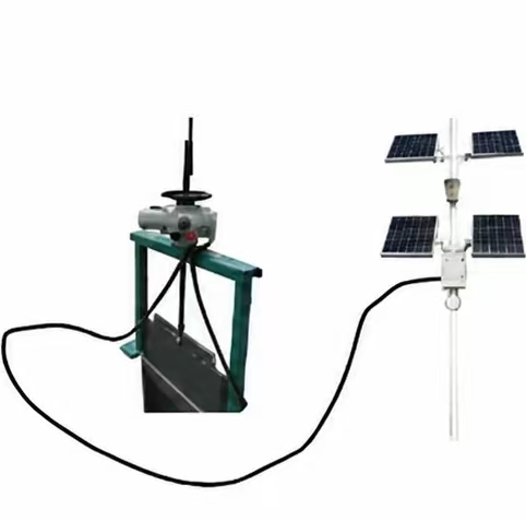
The supplied product materials show electric actuated valves integrated with wind and solar power equipment.
This configuration combines renewable energy supply with electric valve operation, intelligent control and remote communication.
10.4 Solar-Powered Configuration
The supplied materials also show solar-powered configurations for remote valve control systems.
Solar-powered equipment can be incorporated into the system according to the field installation and project configuration.
XI. Applications
11.1 Water Treatment
The supplied IoT system documentation identifies water treatment as one of the field applications for the monitoring and control system.
Valves and related field equipment can be connected to the IoT network for remote monitoring and control.
11.2 Irrigation Systems
Irrigation systems are also shown as an application within the industrial IoT field network.
Wireless communication and remote monitoring can be incorporated into field valve control systems.
11.3 Agricultural Irrigation
The supplied case study materials show an application site using solar-powered electric valves in agriculture and irrigation.
11.4 Aquaculture Farms
A supplied case study also shows a solar-powered wireless control system used at aquaculture farms.
11.5 Remote Field Installations
The combination of wireless communication, remote monitoring and renewable energy integration provides a configurable system for field installations where equipment needs to communicate with a remote monitoring platform.
XII. Case Studies
12.1 Tianjin Salt Lake Project
The supplied project materials include on-site photos from the Tianjin Salt Lake Project.
The case study shows field installations using solar-powered equipment together with monitoring and control infrastructure.
12.2 Tianjin Salt Lake IoT Monitoring Platform
The project materials also show the Tianjin Salt Lake IoT Monitoring and Control Software Platform.
The platform interface demonstrates centralized monitoring, equipment information management and operating data visualization.
12.3 Agricultural Irrigation Application
The supplied field photos show solar-powered electric valve equipment installed for agricultural and irrigation applications.
12.4 Aquaculture Application
The case study materials show a solar-powered wireless control system installed at an aquaculture farm.
12.5 Wireless Control at the Port Terminal
The supplied case studies also include an application of a wireless spray system at the port terminal, demonstrating another field application of the wireless control system.
XIII. Integrated Remote Valve Management
13.1 Valve Control + Wireless Communication + IoT
The Mobile Phone Wireless Controlled Electric Actuated Gate Valve can be incorporated into a broader intelligent monitoring and control system.
The overall architecture brings together:
Electric Valve + Wireless Communication + Field Instruments + Remote Monitoring + Cloud Platform
13.2 Flexible System Configuration
Different field applications may require different communication methods, instruments and control functions.
The system can therefore be configured according to:
- Field communication conditions
- Required control functions
- Connected instruments
- Monitoring parameters
- Power supply conditions
- Cloud platform requirements
- Third-party system integration requirements