
I. Product Introduction
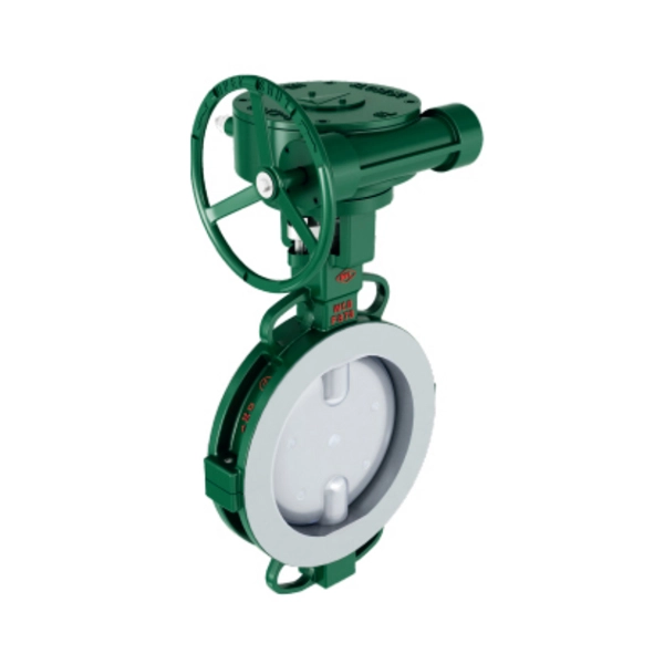
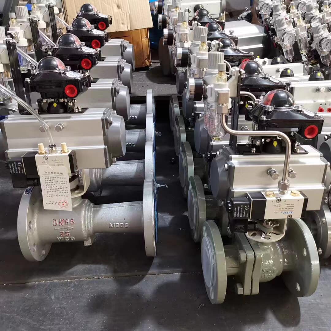
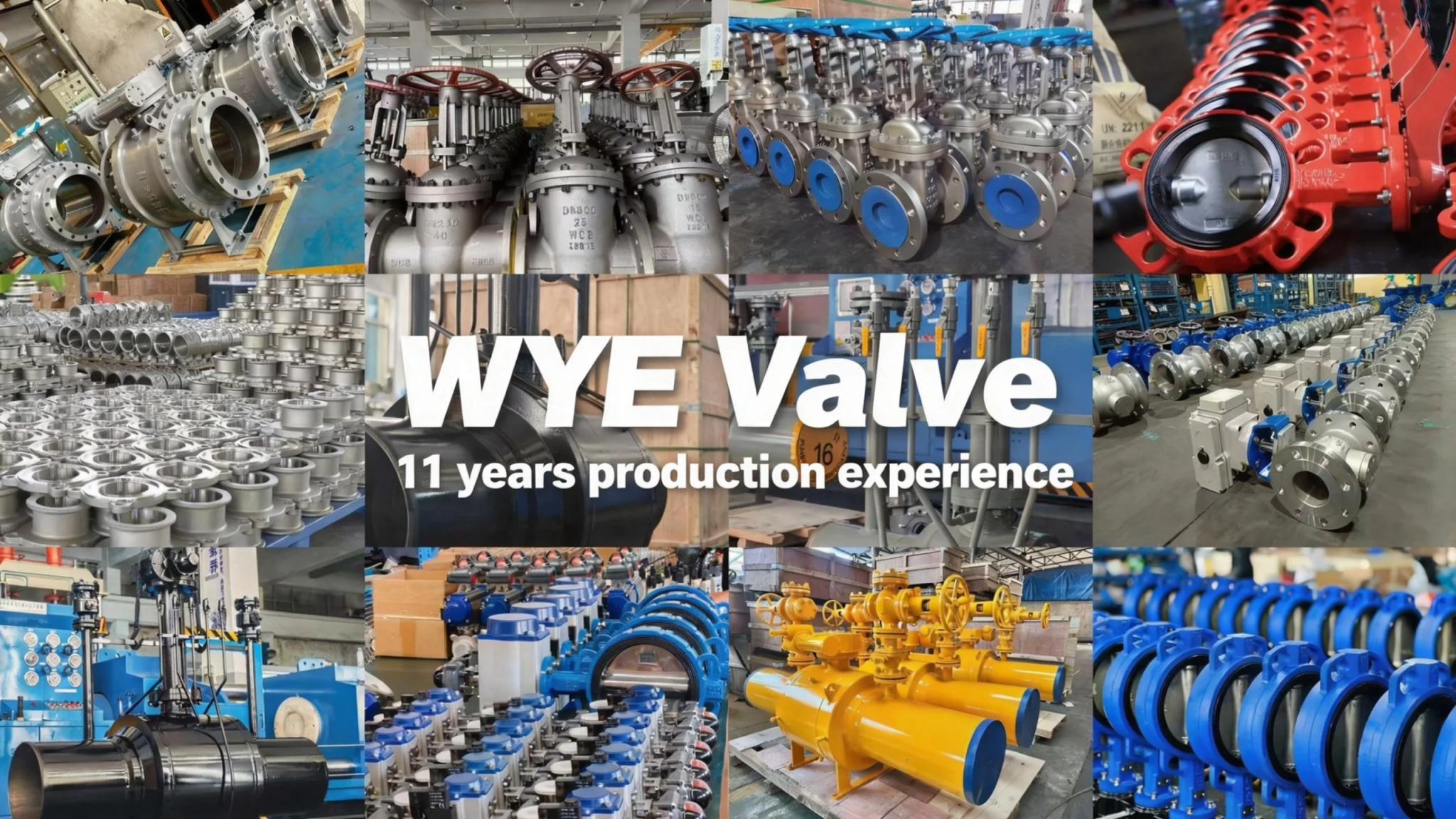
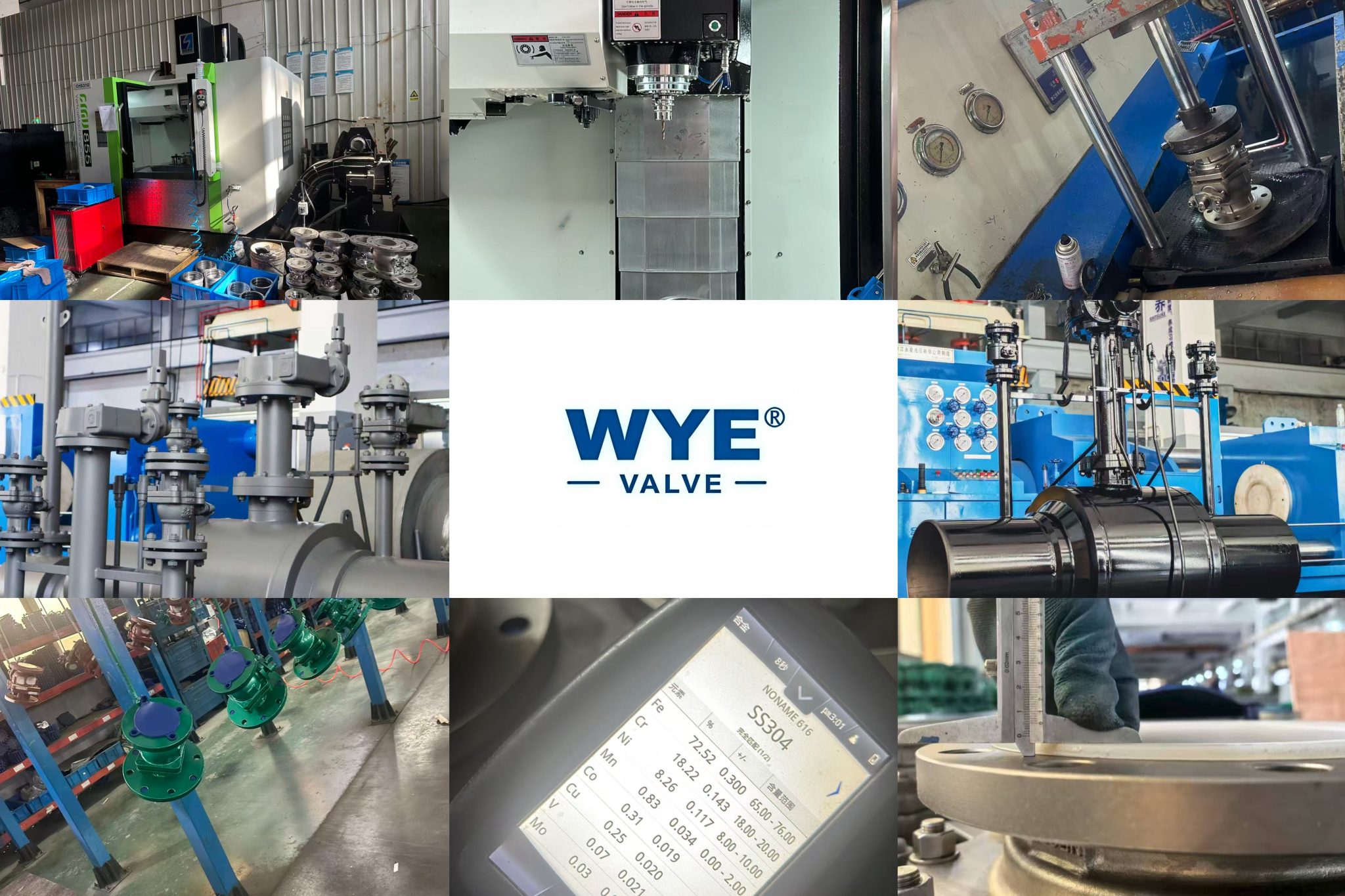
The Worm Gear Clamped End Vertical Plate (Centreline) Butterfly Valve is a high-performance control valve designed for precise regulation and on-off control of various media in industrial pipelines. It adopts a centerline structure and worm gear drive mode, combined with clamped end connection, which ensures stable operation, reliable sealing, and convenient installation. This valve is widely used in chemical, petroleum, pharmaceutical, food and beverage, water treatment, and other industries, and can adapt to different working conditions such as corrosive, high-temperature, and high-pressure media.
The core design of the valve focuses on improving operational efficiency and extending service life. The worm gear transmission mechanism provides a large transmission ratio, enabling users to achieve easy and labor-saving operation even for large-diameter valves. The vertical plate (centreline) structure ensures that the butterfly plate rotates around the centerline of the valve body during opening and closing, minimizing friction between the butterfly plate and the valve seat, thereby reducing wear and improving sealing performance. Meanwhile, the clamped end connection method simplifies the installation process, saves pipeline space, and facilitates later maintenance and replacement.
II. Product Features
-
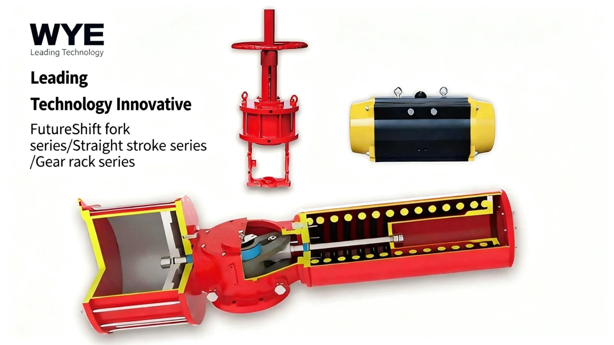
Efficient and Labor-Saving Transmission: Equipped with a high-precision worm gear transmission mechanism, it has the characteristics of large transmission ratio, stable operation, and low noise. It can convert small input torque into large output torque, realizing easy operation of the valve, especially suitable for large-diameter and high-pressure working conditions.
-
Reliable Sealing Performance: Adopting a centerline structure design, the butterfly plate and valve seat are evenly stressed during the opening and closing process, and the sealing surface fits closely. Combined with high-quality lining/seat materials (such as PTFE, FEP), it can achieve zero leakage under normal working conditions, effectively preventing media leakage and ensuring the safety of the production process.
-
Excellent Corrosion Resistance: Multiple lining options (PTFE, FEP, PO polypropylene) and a variety of metal material combinations (gray cast iron, carbon steel, stainless steel) are available. The fully lined or semi-lined structure can isolate the medium from the metal parts of the valve body, making the valve suitable for various corrosive media such as acid, alkali, and salt, and greatly improving the service life in harsh environments.
-
Stable Structural Performance: The upper and lower valve bodies and brackets are made of high-strength materials, which have good pressure-bearing capacity and impact resistance. The butterfly plate and the plate shaft are integrated (for semi-lining type), which enhances the structural rigidity of the valve core, avoids deformation during operation, and ensures the stability of the valve’s flow control performance.
-
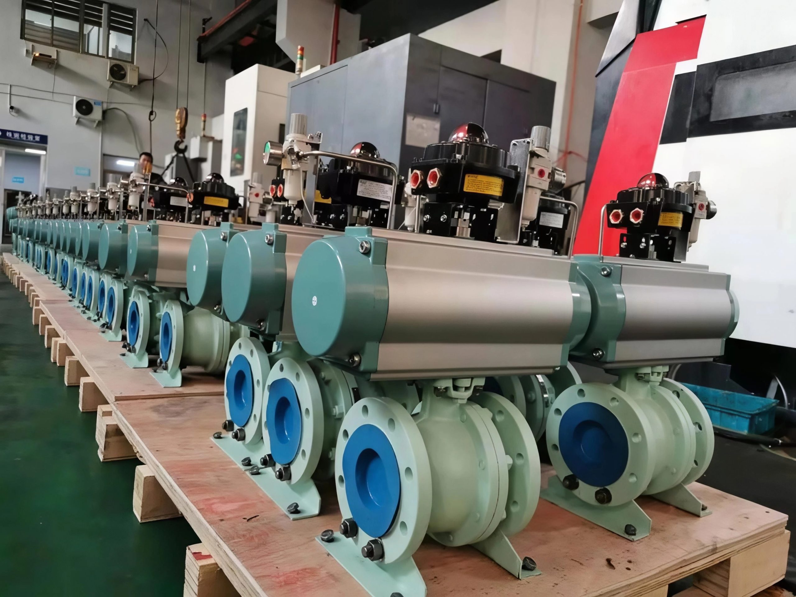
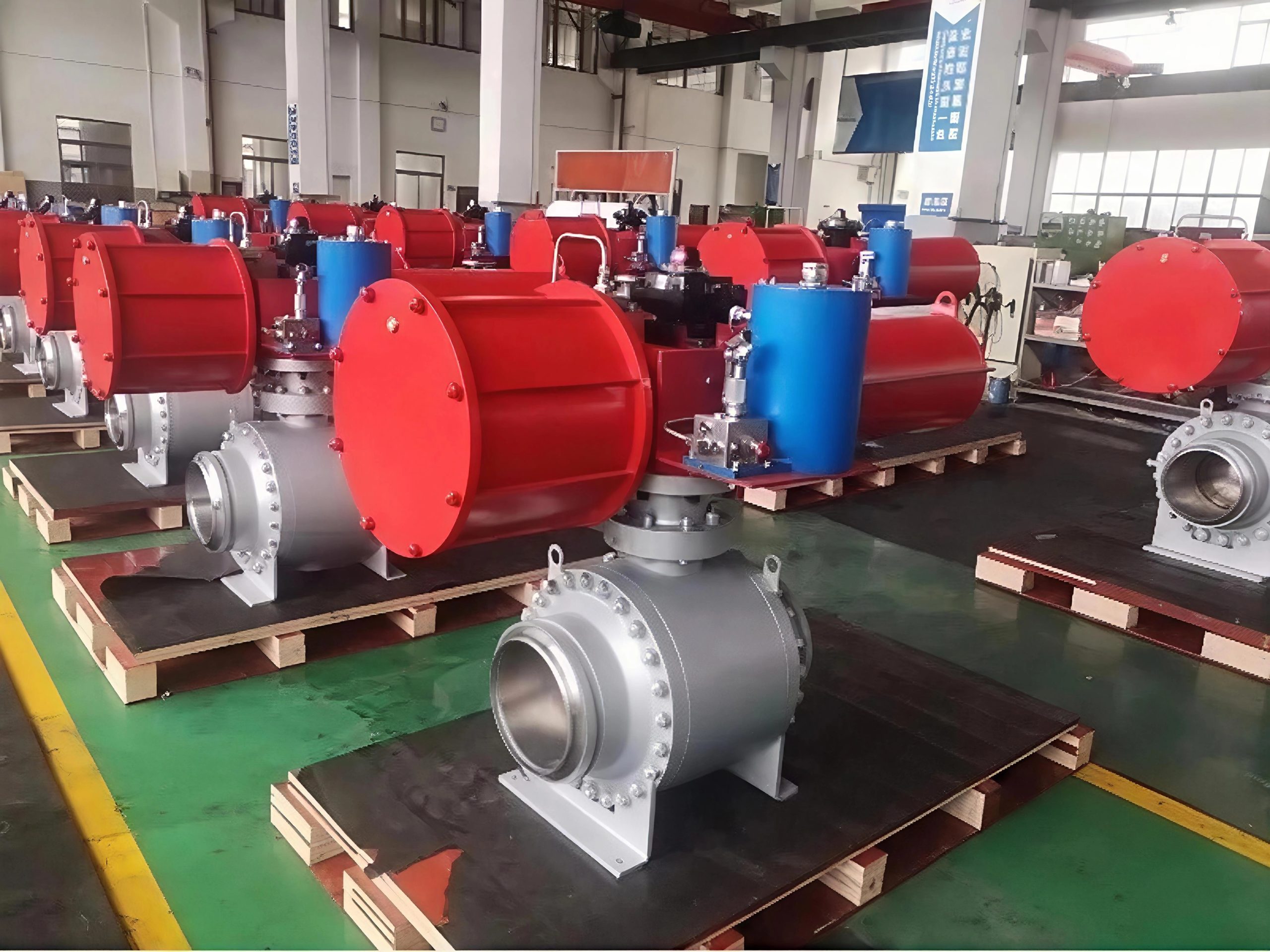
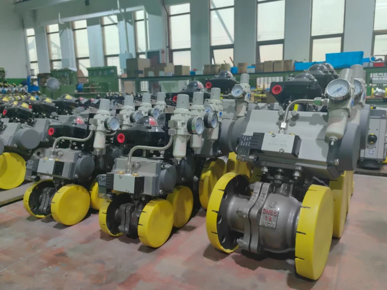
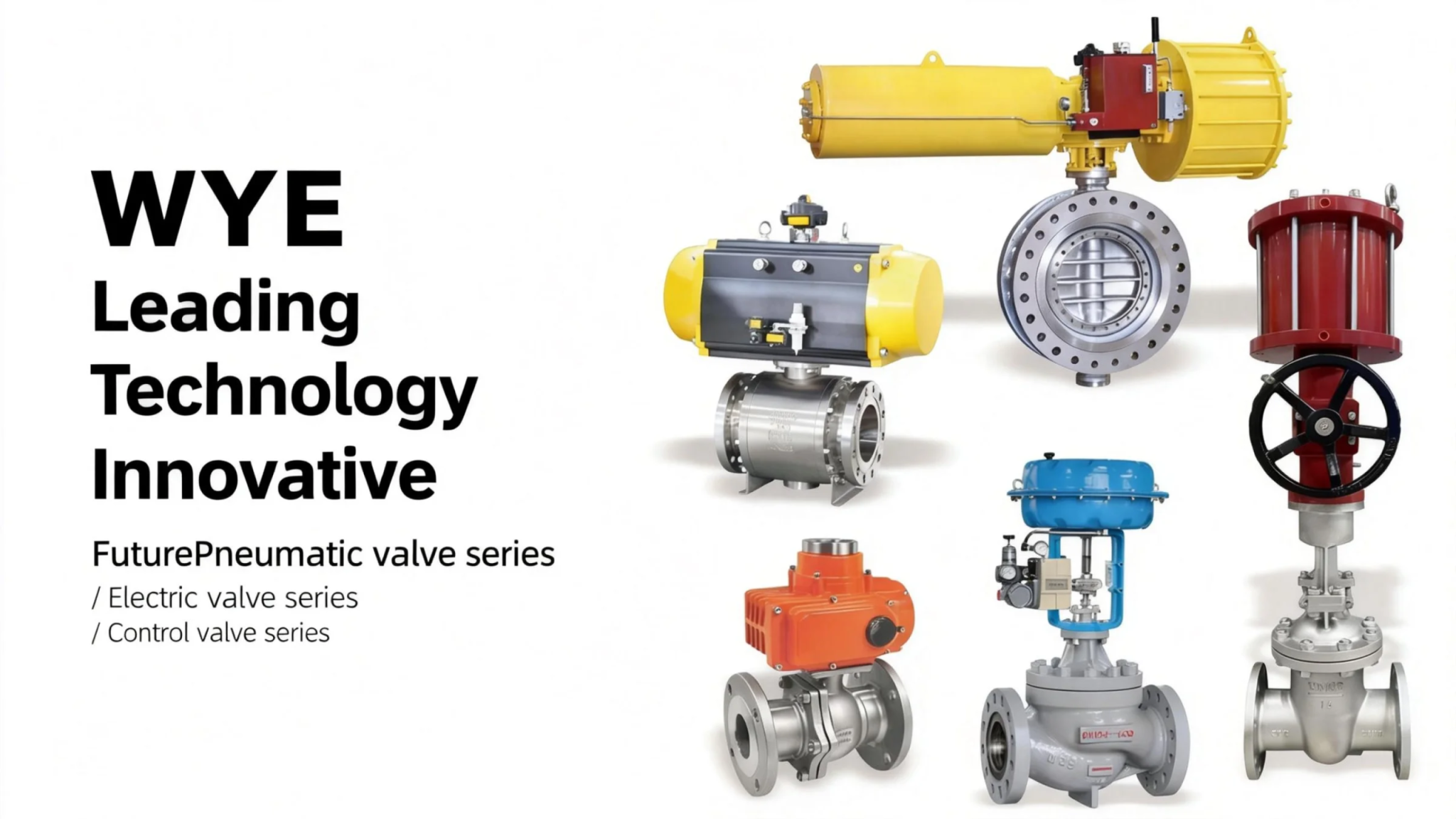
Wide Application Range: It covers a wide range of nominal pressures (PN0.6~1.6MPa) and nominal diameters (DN40~1200mm). There are multiple operation modes such as manual, worm gear rotation, pneumatic, and electric, which can meet the different needs of various industrial pipelines and realize automatic or remote control.
-
Convenient Installation and Maintenance: The clamped end connection is adopted, which is simple and fast to install, without the need for complex flange connection accessories. The internal structure of the valve is simple, the number of parts is small, and the disassembly and assembly are convenient, which reduces the difficulty and cost of later maintenance.
III. Technical Data
3.1 Lining Types & Structural Characteristics
-
a. D371F46 Semi-lining Type: The valve body is fully lined; the butterfly plate is fully lined; the butterfly plate is integrated with the plate shaft. This type combines the advantages of structural stability and corrosion resistance, and the integrated design of the butterfly plate and the shaft ensures reliable transmission and avoids media leakage caused by the gap between the butterfly plate and the shaft.
-
b. D371F4 Fully lined Type: The valve body is fully lined; the butterfly plate is fully lined. The entire flow channel is covered by the lining material, which has the best corrosion resistance and is suitable for strongly corrosive media with high requirements for sealing and corrosion resistance.
-
c. D371F46 Fully lined Valve Body & Unlined Stainless Steel Butterfly Plate: The valve body is fully lined to prevent corrosion of the valve body by the medium; the butterfly plate is made of stainless steel without lining, which has high strength and wear resistance, and is suitable for working conditions where the medium has certain corrosiveness and contains slight solid particles.
3.2 Implementation Standards
-
Design and Manufacturing: GB/T 12238 (median line) / API609
-
Structure Length: GB/T12221 / API609
-
Flange Size: HG/T20592 / ASME B16.5
-
Pressure Test: GB/T13927 / API598
-
Symbolize: GB/T 12220
-
Fill: JB/T 7928
3.3 Basic Models
Nominal Pressure: PN0.6~1.6 (MPa); Nominal Diameter: DN40~1200 (mm)
|
Operation Mode
|
Model Series
|
Lining Type
|
|---|---|---|
|
Manually
|
DA71F/P
|
Semi-Lined
|
|
DA71PFA
|
Fully lined
|
|
|
DA71F4
|
Fully lined
|
|
|
DA71F46
|
Fully lined
|
|
|
Worm-gear Rotation
|
DA371F/P
|
Semi-Lined
|
|
DA371PFA
|
Fully lined
|
|
|
DA371F4
|
Fully lined
|
|
|
DA371F46
|
Fully lined
|
|
|
Pneumatic
|
DA671F/P
|
Semi-Lined
|
|
DA671PFA
|
Fully lined
|
|
|
DA671F4
|
Fully lined
|
|
|
DA671F46
|
Fully lined
|
|
|
Electric
|
DA971F/P
|
Semi-Lined
|
|
DA971PFA
|
Fully lined
|
|
|
DA971F4
|
Fully lined
|
|
|
DA971F46
|
Fully lined
|
3.4 Main Parts and Components Material Table
|
Serial Number
|
Part Name
|
Material (Gray Cast Iron/Z)
|
Material (Carbon Steel/C)
|
Material (Stainless Steel/P)
|
Material (Stainless Steel/R)
|
|---|---|---|---|---|---|
|
1
|
Upper and lower valve body, Bracket
|
HT250
|
WCB
|
CF8
|
CF8M
|
|
2
|
Butterfly plate
|
–
|
WCB
|
CF8
|
CF8M
|
|
3
|
Butterfly plate shaft
|
–
|
25#
|
304
|
316
|
|
4
|
Lining/Seat
|
PTFE (F4), FEP (F46), PO polypropylene
|
|||
|
5
|
Pad
|
SI (silicone rubber)
|
|||
|
6
|
Turbine Box Handle
|
HT250
|
WCB
|
–
|
–
|
Ⅳ.The main shape and connection size
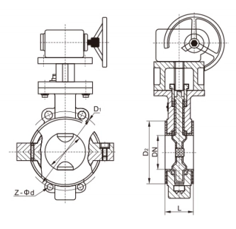
Main connection dimensions and weight
Main connection dimensions and weight


