
BG-GO Series Gas Over Oil Actuators
1. Main application and service scope
1.1 Application
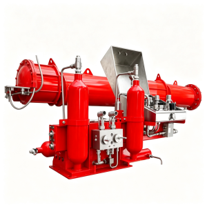
• The BG-GO Series gas over oil Actuator is a rotary actuator specially designed for natural gas pipeline valves. It is suitable for heavy duty on/off service under high-pressure natural gas operating conditions.
• The actuator is powered by high-pressure gas taken directly from the pipeline. It can operate using pipeline pressure(natural gas, acidic gas) or any other gases containing massive hydrogen sulfide(H₂S). It can achieve fully automatic operation in all weather conditions, even at unmanned sites where no external power supply is available.
1.2 Service scope
- Operating Temperature
Standard Types: -20℃ to +80℃ (-4℉ to +176℉)
Customized Manufacture Option 1: -40℃ to +80℃ (-40℉ to +176℉)
Customized Manufacture Option 2: -60℃ to +80℃ (-76℉ to +176℉) - Supply gas pressure
Standard types: operating at a pressure between 10 and 110 bar.
Customized manufacture option for different pressure ranges. - Mounting interface dimensions
Designed in accordance with ISO 5211.
2. Applicable standard
• ISO 5211
3. Performance features
3.1 Torque Range
• The actuator provides an output torque range of 400 to 600,000 Nm.
3.2 Key Advantages
• Based on scotch yoke actuator design
• Compatible with sour gas and gases containing hydrogen sulfide, H₂S
• Wear-resistant and corrosion-resistant design
• Wide torque range
• Modular design
• Robust construction
• Safe and easy to maintain
• Optional local / remote operation
• In case of gas supply failure, a gas storage tank can be equipped to achieve reset operation.
3.3 Applications
• Gas Transmission Pipeline
• Production Lines
• Metering Stations
• Dehydration Systems
• Gas Storage Systems
• Gas Separation Systems
• LNG pipelines
4. Structure parameters
4.1 Main Components of the Actuator
4.1.1 Scotch Yoke Mechanism
• A scotch yoke actuator is used as the primary power transmission mechanism. The scotch yoke mechanism converts the horizontal movement of the hydraulic cylinder into a 90° rotational movement to perform the opening and closing actions.
• Scotch yoke come in two designs: symmetrical and Canted. The symmetrical design produces a symmetrical torque curve, while the Canted design produces a closing-direction torque boost, meeting the varying torque curve requirements of different valves.
4.1.2 Hydraulic Cylinder
• The main power transmission unit transfers power to the scotch yoke mechanism and is operated by hydraulic pressure. The air pressure from the control unit compresses the oil in the hydraulic reservoir, generating a horizontal force on the hydraulic piston.
4.1.3 Gas Hydraulic Tank
• A tank used to store hydraulic Oil and release it as needed through gas compression.
4.2 Standard Accessories
4.2.1 Emergency Manual Pump
• For manual operation in emergencies or when a pneumatic power source is not available. The pump is equipped with a four-way control valve for open, closed, automatic, and bypass positions. It also features a locking mechanism to prevent unauthorized operation. Whenever pneumatic operation is required, the handle should be set to the “AUTO” position; otherwise, the handle should remain in the relevant position to operate the actuator via the manual pump. The bypass position is used to equalize the oil level in the oil tank after the actuator has returned to the middle position.
4.2.2 Hydraulic Filter
• Clean the system oil and adjust the on/off timing.
4.2.3 Undirectional Flow Regulator
• For models equipped with a manual pump, the speed is adjusted using a one-way flow control valve.
4.2.4 Torque limit switch
• The torque generated by the actuator is in direct proportion to the pneumatic pressure. The torque limiter prevents the generation of excessive torque beyond what is required to operate the valve. When the preset value is exceeded, the air pressure is released, preventing the risk of over-torque.
4.2.5 Gas Filter
• All power and pipe gases used in gas over oil actuators are filtered and purified. The micron rating is determined based on specific requirements. Filters should be cleaned regularly depending on frequency of use. More precise filtration systems are available upon request.
4.3 Optional Accessories & Function Modules
4.3.1 Differential Pressure Switch(DP)
• Pneumatic-hydraulic actuators should not be operated under high pressure differentials to prevent damage to the valve and piping. When the pressure differential exceeds the factory-set value, the valve can’t be operated via local or remote control. Opening the valve under high pressure differentials may result in damage to the valve internals and the piping itself. The standard setting range is 17 bar. Other settings rate are available upon request.
4.3.2 Pressure Controlled Emergency Shut-Down (ESD)
• It is used when the actuator is required to shut down the line during emergency condition. ESD system is activated when the pressure drop during break or explosion of pipeline and closes the valve.
• Alternative choices:
• Low Pressure Control (LPS): When control is needed for low pressure opening or closing
• High Pressure Control (HPS): When control is needed for high pressure opening or closing,
• High & Low Pressure Control (LPS&HPS): When control is needed for low and high pressure opening or closing.
4.3.3 Pneumatic Line Break System (PLB)
• It is designed for pipeline breakage control system. It is a process where actuator close the valve automatically once the pressure drop speed is over the preset level. Such as 3.5 bar/min, there is no need or any electrical power to perform this process.
4.3.4 Partial Stroke Test (PST)
• Partial stroke testing is a safety measure for emergency shutdown valves, used to detect faults in ESD valve systems by allowing the ESD valve to perform periodic partial stroke actions. For example, the ESD valve partially closes 10-30% of its stroke from the fully open position, and operates periodically at certain time intervals to better check the movement of its valve stem and determine its functionality. PST is an online method for detecting the reliability of ESD valves.
4.3.5 Electronic Line Break Protection System(ELB)
• Its main function is to automatically acquire and monitor pipeline pressure in real time. In the event of a pipeline abnormality or accident, the system sends a control signal to the actuator to close the valve automatically, ensuring the safety of the pipeline system.
• The configurable functions include:
• Rate of Pressure Drop(ROD) and Increase(ROR)
• Low Pressure(PSL) Opening / Closing; High Pressure(PSH) Opening / Closing
• High Differential Pressure Open Inhibition (requires two pressure sensors.)
• Process Shutdown(PSD), Configurable to exceed all functional requirement
• Partial Stroke Test
• Manual Reset Option After Any Emergency Action
4.3.6 Solar Controller (C)
• For sites without external power supply, a solar controller and solar power supply system can be optionally provide to ensure power supply needs.
4.3.7 Gas Storage Tank (Backup Tank)
• A reservoir tank must be needed if at least one open-close cycle is required when the line pressure is not available.
4.3.8 Fireproof Cover
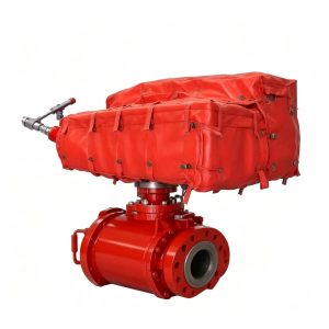
• The risk of fire and explosion is extremely considerable to refinery, gas processing, petrochemical and offshore installations. Fireproof blankets wrap around the actuator and protect it from the harm and damage caused by fire.
5. Selection, Assembly and usage
5.1 Selection of Actuator
The following information is needed when selecting the actuator:
1. Torque values of the valve: Break Torque to Open (BTO), Run Torque to Open (RTO), Run Torque to Close (RTC). Selected actuator should have a 40% torque value over than the max torque of the valve.
2. Flow direction and gas pressure (max, min, normal).
3. Valve stem diameter & dimension of connection key.
4. Actuator connecting flange standard as per ISO5211, or short code(FXX) or dimensions.
5. Valve Datasheets & Actuator Datasheets should be reviewed & answered in details. Additional requirements should be indicated.
5.2 Assembly
Assembly of GO actuator on the valve should be executed by an experienced & qualified team. Moreover it should be checked the suitability of mounting-flanges & stem diameter and actuator is mounted on the valve by lifting through its hooks. Valve with actuator shall be assembled between the proper space left on the pipeline, considering up and down-stream direction. Authorized supervisor would witness the assembly and make the necessary adjustments.
5.3 Usage
The actuator is designed for automatic on-off operation of pipeline valves. It is not suitable for throttling / regulating service.
6. Maintenance and storage
6.1 Maintenance
All GO actuators should be undergo a periodic maintenance annually. Authorized service team would strongly recommended to inspect the gas filters, oil levels, hydraulic hand pump etc. and to review any defected item. Calibration of LB , ESD, torque limit pressure adjustments should be also considered.
6.2 Service
Whenever service is required, Authorized service team is always ready to collaborate. Our professional and qualified service team is ready 24 hours. Emergency response is provided within 24 hours, and remote solutions can be offered for special situations and geographical obstacles.
6.3 Warranty
Provide a period of 24 months warranty for the actuators from the date of shipment. The warranty is effective with assembly, maintenance, start-up and operation.
Important Notice
This catalogue is applicable to Rotary gas-over-oil actuators. Linear gas-over-oil actuators can be provided upon request. Please contact us for any other special requirements.
